Solid-State Synthesis of Nanomaterials: Fundamentals, Methods, and Biomedical Applications
This article provides a comprehensive overview of solid-state synthesis, a cornerstone technique for creating nanomaterials crucial for advanced applications in drug development, energy storage, and electronics.
Solid-State Synthesis of Nanomaterials: Fundamentals, Methods, and Biomedical Applications
Abstract
This article provides a comprehensive overview of solid-state synthesis, a cornerstone technique for creating nanomaterials crucial for advanced applications in drug development, energy storage, and electronics. It covers the foundational principles of solid-state reactions, explores modern methodological advances and their specific applications, addresses common synthesis challenges with practical optimization strategies, and presents validation techniques for comparing material properties. Tailored for researchers, scientists, and drug development professionals, this guide bridges theoretical knowledge with practical implementation to accelerate the development of high-performance nanomaterials.
Core Principles and Material Fundamentals of Solid-State Synthesis
Defining Solid-State Synthesis and its Role in Nanomaterial Fabrication
Solid-state synthesis represents a cornerstone methodology in the field of nanomaterials research, enabling the creation of functional materials with dimensions between 1 and 100 nanometers that exhibit unique thermal, mechanical, electrical, optical, and chemical properties compared to their bulk counterparts [1]. This approach belongs to the top-down synthesis paradigm, where nanomaterials are produced by reducing the size of bulk material until reaching the nanoscale [2]. Unlike bottom-up techniques that build nanostructures from molecular precursors, solid-state synthesis methods involve the physical or mechanical processing of bulk materials to achieve nanoscale dimensions through controlled fragmentation and size reduction processes [1] [2].
The significance of solid-state synthesis has grown substantially with the expanding nanotechnology market, which stood at $7.27 billion in 2017 and is expected to maintain a compound annual growth rate (CAGR) of 17% from 2018 to 2023 [2]. This growth is largely driven by increased demand from various end-use industries including electronics, textiles, pharmaceuticals, energy, aerospace, biotechnology, and food processing [2]. Solid-state synthesis methods provide crucial manufacturing pathways to meet this escalating demand for nanomaterials across diverse applications.
Fundamental Principles and Methodologies
Core Mechanism of Solid-State Synthesis
Solid-state synthesis operates on the principle of top-down nanofabrication, where bulk starting materials are systematically reduced to nanoscale dimensions through the application of mechanical forces, thermal energy, or other physical processes [1] [2]. When a bulk material is fragmented to nano-dimensions, electrons become subjected to peculiar boundary conditions, leading to the emergence of special properties not observed in bulk counterparts [1]. This quantum confinement effect fundamentally alters the electronic structure of materials, resulting in unique optical, electrical, and thermal behaviors that can be exploited for various applications [1].
The process typically begins with bulk or micron-sized precursor materials that undergo successive size reduction stages. Unlike bottom-up approaches that rely on molecular self-assembly or chemical reduction of precursors, solid-state methods directly transform macroscopic material into nanostructures through physical processes [1]. This approach permanently modifies the starting material's structure, often introducing structural imperfections and crystallographic defects on the surface of the resulting nanostructures [1]. While these imperfections can sometimes limit long-range homogeneity, they may also introduce beneficial properties for certain applications such as catalysis or energy storage.
Classification of Solid-State Synthesis Techniques
Solid-state synthesis encompasses multiple technical approaches that facilitate nanomaterial production:
- Mechanical Methods: These techniques rely primarily on mechanical forces to achieve size reduction, including ball milling and mechanochemical processing [2]
- Thermal Methods: Utilizing controlled thermal treatments to induce structural changes or phase segregation at nanoscale [2]
- Ablation Methods: Employing directed energy sources like lasers to remove material and create nanostructures [1]
- Solid-State Segregation: Based on mixing precursors in liquid glass melts at high temperature, followed by cooling to phase transition temperature to form nanoparticles through nucleation [2]
Table 1: Major Solid-State Synthesis Techniques for Nanomaterials
| Method | Key Principle | Typical Size Range | Materials Compatibility |
|---|---|---|---|
| Mechanical Ball Milling [1] [2] | Size reduction through grinding media impact | 2-100 nm | Metals, alloys, ceramics, composites |
| Mechanochemical Milling [2] | Chemical reactions induced by mechanical energy | 10-100 nm | Wide range of precursors including oxides, carbonates, sulfates |
| Laser Ablation [1] | Material removal using focused laser pulses | 1-100 nm | Metals, semiconductors, dielectrics, ceramics |
| Solid-State Segregation [2] | Nucleation from supersaturated melt | 1-20 nm (quantum dots) | Metals, semiconductors |
Key Experimental Protocols and Methodologies
Mechanical Ball Milling Protocol
Mechanical ball milling represents one of the most established solid-state synthesis techniques, dating back to the 1970s for producing nanostructured powders [2]. The standard experimental protocol involves:
Apparatus Setup: The process utilizes a grinding jar (cylindrical container) filled with grinding media, typically hardened steel or tungsten carbide balls with various diameters [1] [2]. Different mill types include tumbler mills, attrition mills, shaker mills, vibratory mills, and planetary mills, each offering distinct motion patterns and energy input characteristics [2].
Material Preparation: The precursor material in powder form (typically ~50 µm diameter) is placed in the grinding jar along with the grinding media [1]. A mass ratio of 5:10 for balls to powder is commonly maintained to optimize impact efficiency [2]. In some cases, supporting chemicals or process control agents like toluene are added to facilitate smooth grinding and prevent agglomeration [2].
Milling Parameters: The jar is rotated or oscillated at controlled speeds (revolutions per minute) for predetermined time durations [1]. The kinetic energy transfer depends on the mass and velocity of the grinding media, with high-density materials preferred for efficient size reduction [2]. The process can achieve grain size reduction from initial 50-100 µm down to 2-20 nm through repeated impact and shear forces [2].
Post-Processing: The resulting nanomaterial powder is collected and may undergo additional classification or purification steps to isolate specific size fractions. The process typically works at low temperatures, resulting in slow grain growth and facilitating the formation of stable nanostructures [2].
Solid-State Segregation for Quantum Dot Synthesis
Solid-state segregation represents a specialized solid-state approach particularly suited for producing quantum dots of metals and semiconductors [2]. The experimental workflow involves:
Precursor Preparation: Precursor materials are meticulously weighed and mixed in precise stoichiometric ratios appropriate for the target nanomaterial composition [2].
Melting and Homogenization: The precursor mixture is heated in a liquid glass melt at elevated temperatures until complete homogenization is achieved [2]. Temperature control during this phase is critical for ensuring uniform distribution of precursor components.
Controlled Cooling: The homogeneous melt is gradually cooled to the phase transition temperature, creating supersaturation conditions for the precursor materials [2]. The cooling rate significantly influences nucleation density and subsequent nanoparticle size distribution.
Nucleation and Growth: Under supersaturation conditions, nucleation occurs spontaneously, followed by nanoparticle growth through diffusion processes within the solid matrix [2]. This method has been successfully employed for producing nanocrystalline cobalt aluminate (CoAl₂O₄) nanoparticles used as inorganic ceramic blue pigments [2].
Laser Ablation in Liquid (LAL) Synthesis
Laser ablation in liquids combines aspects of both top-down and bottom-up approaches [1]. The methodology involves:
Target Preparation: A bulk solid target of the material to be converted to nanoparticles (metal, semiconductor, or insulator) is immersed in a liquid medium [1]. The target typically requires only minimal surface cleaning without sophisticated preparation.
Laser Parameters: A high-peak power pulsed laser (not continuous wave) is focused onto the target surface through the liquid medium [1]. Laser parameters including wavelength, pulse duration, repetition rate, and fluence significantly influence the ablation process and resulting nanoparticle characteristics.
Ablation Process: The focused laser pulses locally heat the target material, leading to plasma formation and ejection of nanoscale fragments into the surrounding liquid [1]. The liquid medium serves to confine the plasma and collect the ejected nanoparticles, often providing stabilization through surface interactions.
Collection and Processing: The colloidal suspension of nanoparticles in the liquid medium can be used directly or processed further through centrifugation, filtration, or concentration steps [1]. This green synthesis approach avoids chemical surfactants and produces gram-scale quantities of pure nanomaterials free from chemical contaminants [1].
Characterization of Synthesized Nanomaterials
The evaluation of nanomaterials produced through solid-state synthesis requires comprehensive characterization to confirm structural features, composition, and functional properties. Advanced characterization tools have been instrumental in driving nanotechnology forward, enabling investigation of materials as small as 0.2 nm [2].
Structural Analysis: Transmission electron microscopy (TEM) and atomic force microscopy (AFM) provide direct visualization of nanoparticle size, morphology, and distribution [2]. These techniques allow researchers to verify successful achievement of nanoscale dimensions and assess the homogeneity of the synthesized materials.
Crystallographic Characterization: X-ray diffraction (XRD) analysis determines crystal structure, phase purity, and crystallite size through line broadening analysis [2]. This is particularly important for solid-state synthesized nanomaterials where structural imperfections may be introduced during processing [1].
Surface Analysis: The large surface-to-volume ratio represents a key characteristic of nanomaterials, significantly influencing their reactivity and properties [2]. Surface area analysis through gas adsorption techniques and surface composition analysis through X-ray photoelectron spectroscopy provide crucial information about surface properties.
Table 2: Key Properties and Applications of Solid-State Synthesized Nanomaterials
| Material Type | Key Properties | Solid-State Synthesis Method | Representative Applications |
|---|---|---|---|
| Metal-Organic Frameworks (MOFs) [2] | Large surface area, internal volume | Mechanochemical milling | Catalysis, separations, gas storage |
| Bi-based nanomaterials [2] | Thermoelectric, optical, magnetoresistance | Ball milling, solid-state segregation | Thermoelectric devices, optical devices, GMR, superconductivity |
| MoS₂ nanomaterials [2] | Lubrication enhancement, catalytic activity | Mechanical exfoliation, milling | Additives for base oils, catalysts |
| Cobalt aluminate (CoAl₂O₄) [2] | Optical properties, color intensity | Solid-state segregation | Ceramic blue pigments, paint, glass, color filters |
Current Research Advances and Synthesizability Prediction
Recent advances in solid-state synthesis research have increasingly incorporated data-driven approaches to predict and optimize nanomaterial synthesizability. The experimental validation of candidate materials represents a significant bottleneck in materials discovery, leading researchers to develop computational methods to prioritize the most promising candidates [3].
Synthesizability Prediction: Machine learning approaches, particularly positive-unlabeled (PU) learning, have shown promise in predicting the solid-state synthesizability of hypothetical compounds [3]. These models address the challenge of limited reported data on failed synthesis attempts by learning from positive examples (successfully synthesized materials) and unlabeled data [3].
Thermodynamic Stability Metrics: The energy above the convex hull (Eₕᵤₗₗ) serves as a popular proxy for material synthesizability, representing the difference between the formation enthalpy of the material and the sum of the formation enthalpies of its most stable decomposition products [3]. However, Eₕᵤₗₗ alone is insufficient for predicting synthesizability, as kinetic barriers and synthesis conditions significantly influence experimental outcomes [3].
Human-Curated Data Integration: The creation of manually curated datasets containing synthesis information for ternary oxides has enabled more accurate prediction models [3]. For instance, a dataset of 4103 ternary oxides with detailed synthesis information has been used to identify outliers in text-mined datasets and train improved synthesizability prediction models [3].
Text-Mining and Natural Language Processing: Automated extraction of synthesis information from scientific literature using NLP techniques has created large-scale datasets for training predictive models [3]. However, quality issues remain significant, with one major text-mined dataset showing only 51% overall accuracy in extracted synthesis conditions and actions [3].
The Scientist's Toolkit: Essential Research Reagents and Materials
Successful implementation of solid-state synthesis protocols requires specific materials and equipment. The following table details essential components for establishing solid-state synthesis capabilities.
Table 3: Essential Research Reagents and Equipment for Solid-State Synthesis
| Item | Function/Role | Specifications/Examples |
|---|---|---|
| Grinding Media [2] | Size reduction through mechanical impact | Hardened steel, tungsten carbide balls; Various diameters for optimal size reduction |
| Precursor Materials [2] | Source materials for nanomaterial synthesis | Metals, alloys, oxides, carbonates, sulfates, chlorides, fluorides in powder form (~50 µm) |
| Process Control Agents [2] | Facilitate smooth grinding, prevent agglomeration | Toluene or other appropriate solvents; Surface-modifying agents |
| High-Temperature Furnaces [2] | Thermal processing for solid-state reactions | Controlled atmosphere capability; Precise temperature control up to 1600°C |
| Pulsed Laser System [1] | Ablation of target materials for LAL synthesis | High-peak power pulsed lasers; Appropriate wavelength for target material |
| Liquid Media [1] | Environment for laser ablation, stabilization | Deionized water, organic solvents; Provides cooling and nanoparticle collection |
Workflow and Process Diagrams
Diagram 1: Solid-State Synthesis Workflow
Diagram 2: Solid-State Synthesis Classification
Solid-state synthesis represents a fundamental manufacturing paradigm within nanomaterials research, providing essential pathways for producing functional nanostructures across diverse material systems. While the approach offers advantages in scalability and direct processing of bulk materials, it faces challenges related to structural imperfections, size distribution control, and long-range homogeneity [1]. The ongoing integration of data-driven approaches, synthesizability prediction models, and automated experimental validation promises to address these limitations and accelerate nanomaterials discovery [3].
As the nanotechnology market continues its rapid expansion, solid-state synthesis methodologies will play an increasingly critical role in bridging laboratory-scale research and industrial-scale production [2]. Future advancements will likely focus on improving control over nanoparticle size and morphology, reducing structural defects, and developing hybrid approaches that combine the strengths of both top-down and bottom-up strategies [1] [2]. Through continued refinement of these fundamental fabrication techniques, solid-state synthesis will maintain its position as an indispensable tool in the nanomaterials research toolkit.
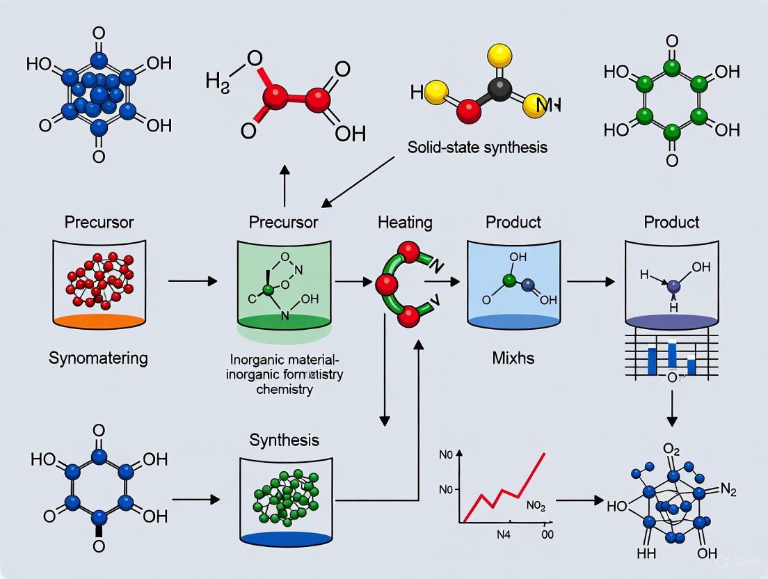
Solid-state synthesis is a foundational methodology in nanomaterials research, characterized by the direct reaction of solid precursors at elevated temperatures to form new solid-phase products. This technique is particularly valued for producing a wide array of inorganic nanomaterials, including metal oxides, semiconductors, and complex ceramic compounds. The process typically involves the meticulous mixing of precursor powders, followed by a series of heat treatments at high temperatures to facilitate diffusion and solid-state reaction, ultimately yielding a crystalline nanomaterial [4]. Within the broader context of nanomaterial fabrication, solid-state synthesis is classified as a top-down approach, where bulk materials are transformed into nanostructured forms through physical processing or chemical reactions [5]. Its fundamental principles make it exceptionally suited for achieving high yield, superior efficiency, and seamless integration with automated industrial processes, which are critical demands in modern research and production environments, including pharmaceutical development [6].
Core Principles and Methodological Framework
The efficiency and success of solid-state synthesis are governed by several core principles centered on atomic diffusion and reaction kinetics. The process initiates with the intimate mixing of reactant powders to maximize particle contact. Upon heating, atomic or ionic diffusion across the interfaces of the reactant particles occurs, leading to the nucleation and growth of the desired product phase. The reaction kinetics are inherently influenced by factors such as temperature, particle size of the precursors, and the pressure applied during milling or pressing. Finer precursor particles, for instance, provide a greater surface area for reaction, significantly enhancing the kinetics and overall yield [4].
A representative experimental protocol for the solid-state synthesis of a semiconducting nanomaterial, as detailed in a study on the CuTa2-xSbxO6 solid solution, is outlined below [4]:
- 1. Precursor Preparation: High-purity powders of the starting materials (e.g., CuO, Ta
2O5, and α-Sb2O4) are accurately weighed in stoichiometric proportions according to the desired final composition (e.g., x = 0.10 to 0.50 in CuTa2-xSbxO6). - 2. Mechanochemical Mixing: The precursor powders are subjected to intensive mechanical mixing and grinding. This critical step ensures homogeneity at the microscopic level, which is vital for a uniform and complete reaction.
- 3. Calcination: The homogeneously mixed powder is placed in a high-temperature furnace and heated (typically in air) at a controlled rate to a specified calcination temperature. This temperature is maintained for a prolonged period (often several hours to days) to allow the solid-state reaction to proceed to completion.
- 4. Product Characterization: The resulting solid product is systematically analyzed using techniques such as X-ray Diffraction (XRD) to confirm phase formation and crystal structure, Differential Thermal Analysis (DTA) to study thermal stability, and UV-Vis Diffuse Reflectance Spectroscopy (UV-Vis-DRS) to determine functional properties like the energy band gap.
The following workflow diagram illustrates the logical progression and decision points in a standard solid-state synthesis protocol.
Quantitative Analysis of Advantages
The merits of solid-state synthesis can be quantitatively evaluated against other common nanomaterial synthesis methods, such as bottom-up self-assembly or microfluidics-assisted synthesis [7] [8]. The tables below summarize key performance metrics and a comparative analysis.
Table 1: Performance Metrics of Solid-State Synthesis
| Metric | Typical Range/Outcome | Evidence/Example |
|---|---|---|
| Reaction Yield | High mass yield, often >95% for optimized reactions | Successful formation of CuTa2-xSbxO6 solid solution across the range 0 < x ≤ 0.5 [4] |
| Process Efficiency | Efficient for large-scale production of inorganic materials | Conventional method for synthesizing oxide semiconductors and ceramics [5] [4] |
| Scalability | Highly scalable from gram to kilogram batches | Direct scalability from lab-based furnace to industrial kiln [6] |
| Automation Potential | High; easily integrated into continuous processing lines | Suitability for integration into Continuous Manufacturing (CM) frameworks [6] |
Table 2: Comparative Analysis with Other Synthesis Methods
| Method | Key Advantage | Key Disadvantage |
|---|---|---|
| Solid-State Synthesis | High yield, simplicity, scalability, suitability for thermodynamically stable phases [4] | High energy consumption, potential for inhomogeneity, limited control over nano-morphology [5] |
| Bottom-Up Self-Assembly | Precision and programmability at the nanoscale, complex architectures [7] | Lower yield, often requires specific solvents/ligands, scalability challenges [5] [7] |
| Microfluidics-Assisted | Superior control over size, polydispersity, and complex formulations [8] | Lower volumetric throughput, potential for channel clogging, more complex equipment [8] |
The Scientist's Toolkit: Essential Research Reagents
The following table details key reagents and materials commonly employed in solid-state synthesis experiments, along with their critical functions.
Table 3: Essential Reagents and Materials for Solid-State Synthesis
| Item | Function in the Protocol |
|---|---|
| Metal Oxide Precursors | Serve as the primary source of metal cations for the reaction. Their purity and particle size directly impact product stoichiometry and reaction kinetics. |
| High-Temperature Crucibles | Contain the reaction mixture during calcination. They must be chemically inert and thermally stable at the maximum process temperatures. |
| Ball Milling Apparatus | Provides the mechanical energy for the mechanochemical mixing step, ensuring homogeneity and reducing precursor particle size. |
| Programmable Furnace | Provides the controlled high-temperature environment necessary for the solid-state diffusion and reaction to occur. |
Pathway to Automation and Continuous Manufacturing
The inherent batch-based nature of traditional solid-state synthesis is being transformed by the principles of Continuous Manufacturing (CM). CM is a production process characterized by the uninterrupted input of raw materials and output of finished product, offering significant advantages over batch processing [6]. The diagram below illustrates how a solid-state synthesis process can be integrated into an automated CM framework.
The drivers for adopting CM in nanomaterial production are compelling. Studies indicate that CM can lead to operational cost savings of 6–40% and capital cost reductions of 20–75% compared to traditional batch operations [6]. Furthermore, an analysis of pharmaceutical products revealed that those utilizing CM experienced significantly shorter times to regulatory approval and market entry, translating to hundreds of millions of dollars in additional revenue [6]. The integration of Process Analytical Technology (PAT) tools, such as in-line spectrometers and sensors, allows for real-time monitoring and control of Critical Quality Attributes (CQAs), ensuring consistent product quality and facilitating rapid process optimization [6].
Solid-state synthesis remains a cornerstone technique for the production of inorganic nanomaterials, distinguished by its high yield, operational efficiency, and straightforward scalability. Its compatibility with the emerging paradigm of Continuous Manufacturing, bolstered by advanced process monitoring and control, positions it as a critical methodology for the future of industrial nanomaterial production. As the demand for high-quality nanomaterials grows across sectors from electronics to medicine, the evolution of this foundational technique towards greater automation and intelligence will be instrumental in meeting the dual challenges of scale and precision.
Solid-state synthesis is a cornerstone of modern inorganic chemistry and nanomaterials research, underpinning the development of countless functional materials for applications ranging from electronics to biomedicine [5] [9]. Unlike solution-phase reactions where solvents facilitate molecular mixing, solid-state reactions occur through direct atomic diffusion between solid precursors, making them highly dependent on specific processing parameters [10]. The fundamental challenge in solid-state synthesis lies in predicting and controlling reaction outcomes, as these processes typically proceed through a series of intermediate phases whose formation is governed by a complex interplay of thermodynamic and kinetic factors [10] [9]. The transformative potential of nanomaterials across scientific and engineering disciplines is heavily dependent on the precise control of their physicochemical properties through carefully optimized synthesis protocols [5].
This technical guide examines the critical process parameters of temperature, pressure, and reaction kinetics within the context of solid-state synthesis for nanomaterials research. For drug development professionals and materials scientists, understanding these parameters is essential for designing synthesis routes that yield materials with targeted characteristics. The pathway taken by a solid-state reaction is often determined by the initial phase that forms, as it consumes much of the free energy associated with the starting materials, thereby dictating subsequent reaction evolution [10]. Recent advances in characterization techniques and computational modeling have significantly enhanced our understanding of how these parameters influence synthesis outcomes, enabling more rational design of nanomaterial fabrication protocols [9] [11].
Temperature as a Critical Parameter
Temperature exerts profound influence on solid-state reactions through its effects on reaction kinetics, diffusion rates, and thermodynamic driving forces. In classical nucleation theory, the nucleation rate (Q) for a given product follows the relationship:
[Q = A \exp\left(\frac{-16\pi\gamma^3}{3n^2k_BT\Delta G^2}\right)]
where A is a prefactor related to thermal fluctuations and diffusion rates, γ represents interfacial energy, n is atomic density, kB is Boltzmann's constant, T is temperature, and ΔG is the bulk reaction energy [10]. This equation highlights the complex, exponential dependence of nucleation rates on temperature, which directly affects which phases form during synthesis.
The impact of temperature on solid-state reactions is particularly evident in the synthesis of barium titanate (BaTiO3), a crucial material for electronic ceramic components. Traditional solid-phase reactions between BaCO3 and TiO2 typically require temperatures above 1100°C, which leads to significant grain growth and micron-sized particles unsuitable for advanced multilayer ceramic capacitors (MLCCs) [12]. However, systematic investigation of synthesis parameters has demonstrated that optimizing temperature profiles can yield phase-pure BaTiO3 powder with uniform particle size (90 nm) at significantly reduced temperatures of 800°C [12]. This temperature reduction is critical for controlling grain size while improving the tetragonality (c/a ratio) of the powder, ultimately leading to enhanced material properties for electronic applications.
Table 1: Temperature Effects on Barium Titanate Synthesis Outcomes
| Synthesis Temperature (°C) | Particle Size (nm) | Tetragonality (c/a ratio) | Phase Purity | Application Suitability |
|---|---|---|---|---|
| >1100 (Conventional) | >1000 (micron) | Not reported | Phase-pure | Limited for advanced MLCCs |
| 750 | N/A | N/A | 71.11% conversion | Incomplete reaction |
| 800 | 90 | Not reported | Phase-pure | High-end MLCCs |
| 900 | 160 | 1.0095 | Phase-pure | High-end MLCCs |
Advanced characterization techniques, particularly in situ transmission electron microscopy (TEM), have revealed the profound influence of temperature on nanomaterial formation mechanisms. In situ TEM enables real-time observation of dynamic structural evolution during nanomaterial growth at the atomic scale, providing unprecedented insights into temperature-dependent phenomena such as Ostwald ripening, phase separation, and defect evolution [11]. These observations have demonstrated that thermal stability of nanomaterials during synthesis is crucial for maintaining intended properties, as phase transformations under thermal stimuli can fundamentally alter material characteristics [11].
Pressure and Atmosphere Control
Pressure represents another critical parameter in solid-state synthesis, influencing reaction pathways through its effects on decomposition kinetics, thermodynamic driving forces, and intermediate phase stability. Research on barium titanate synthesis has demonstrated that reducing the synthesis pressure to 0.01 MPa significantly enhances the decomposition kinetics of precursor materials, promoting BaCO3 decomposition into BaO and CO2 at lower temperatures [12]. This pressure reduction accelerates the solid-state reaction rate, increasing BaTiO3 conversion to 71.11% at 750°C compared to conventional methods.
The mechanism behind pressure effects involves altering the gas-phase equilibrium in reactions involving gaseous products. In the barium titanate system, the low-pressure environment facilitates the removal of CO2 gas produced during reaction, shifting the equilibrium toward product formation according to Le Chatelier's principle [12]. This effect enables not only reduced synthesis temperatures but also improved material characteristics, as the low-pressure environment limits grain growth while enhancing crystallographic properties such as tetragonality [12].
Table 2: Pressure Effects on Solid-State Synthesis Reactions
| Pressure Condition | Reaction Temperature | Key Effects | Material Outcomes |
|---|---|---|---|
| Atmospheric pressure | High (>1100°C for BaTiO3) | Standard reaction kinetics, possible grain growth | Larger particles, potential impurities |
| Reduced pressure (0.01 MPa) | Lower (750-900°C for BaTiO3) | Enhanced precursor decomposition, limited grain growth | Smaller particle size, improved phase purity |
| Controlled atmosphere (e.g., low pO2) | Variable | Prevents oxidation, controls defect chemistry | Tailored stoichiometry, specific properties |
Beyond direct pressure application, atmosphere control plays a crucial role in determining solid-state reaction outcomes. Murata Manufacturing demonstrated that lowering the partial pressure of oxygen to 2×10² Pa or less enabled preparation of pure-phase BaTiO3 powders at 600°C using specific precursors [12]. Similar atmospheric considerations apply to the synthesis of complex oxides and other functional materials where oxidation states must be carefully controlled throughout the synthesis process.
Reaction Kinetics and Mechanisms
Reaction kinetics in solid-state synthesis governs the progression of phase transformations and ultimately determines the success of synthesis protocols. The Johnson-Mehl-Avrami (JMA) model has proven effective in describing the kinetics of solid-state reactions, enabling researchers to predict reaction progress and optimize milling parameters in mechanochemical synthesis [13]. For instance, kinetics studies of AlH3/MgCl2 nanocomposite formation by mechanical milling of MgH2 and AlCl3 have provided quantitative understanding of transformation fractions under different processing conditions [13].
The concept of "thermodynamic control" has emerged as a critical framework for understanding solid-state reaction pathways. Recent research has established that when the reaction energy for one product exceeds that of all competing phases by ≥60 meV/atom, thermodynamics primarily dictates the initial product formed [10]. This threshold for thermodynamic control has profound implications for predicting synthesis pathways from first principles, with analysis of Materials Project data indicating that approximately 15% of possible reactions fall within this regime [10].
Advanced algorithms like ARROWS3 (Autonomous Reaction Route Optimization with Solid-State Synthesis) now leverage this understanding to automate precursor selection by actively learning from experimental outcomes [9]. This algorithm identifies precursors that avoid highly stable intermediates, thereby retaining larger thermodynamic driving force to form the target material. The implementation of such computational approaches represents a significant advancement in managing the complexity of solid-state reaction kinetics.
In situ characterization techniques have revolutionized our understanding of reaction kinetics by providing real-time observation of phase evolution during synthesis. In situ X-ray diffraction (XRD) studies of the Li-Nb-O chemical space have revealed how different lithium sources (LiOH vs. Li2CO3) lead to distinct reaction pathways due to their differing thermodynamic driving forces [10]. Similarly, in situ TEM has enabled direct visualization of kinetic processes such as atomic migration, interfacial evolution, and structural transformation during nanomaterial synthesis, often revealing significant deviations from classical theoretical predictions [11].
Advanced Characterization and Computational Guidance
In Situ Characterization Techniques
The development of advanced in situ characterization methods has dramatically improved understanding of solid-state synthesis processes. In situ transmission electron microscopy (TEM) enables researchers to observe and analyze dynamic structural evolution during nanomaterial growth at atomic resolution, providing unprecedented insights into nucleation and growth mechanisms [11]. Modern in situ TEM methodologies include heating chips, electrochemical liquid cells, graphene liquid cells, gas-phase cells, and environmental TEM, each facilitating specific types of synthesis observations under controlled conditions [11].
The synergy between in situ TEM and spectroscopic techniques such as energy dispersive X-ray spectroscopy (EDS) and electron energy loss spectroscopy (EELS) allows comprehensive characterization of nanomaterials, capturing not only morphological changes but also chemical composition and electronic structure evolution during synthesis [11]. These capabilities are further enhanced by aberration-corrected lenses and advanced imaging modalities including high-angle annular dark field (HAADF), scanning TEM (STEM), and electron tomography, which collectively provide enhanced spatial resolution and analytical power for investigating synthesis mechanisms [11].
Computational Optimization Approaches
Computational methods have emerged as powerful tools for guiding solid-state synthesis optimization. The ARROWS3 algorithm represents a significant advancement by incorporating physical domain knowledge based on thermodynamics and pairwise reaction analysis to guide precursor selection [9]. This algorithm uses existing thermochemical data from resources like the Materials Project to form initial rankings of precursor sets based on density functional theory (DFT)-calculated reaction energies, then iteratively refines these rankings based on experimental outcomes [9].
Machine learning integration with synthesis optimization has shown remarkable potential for accelerating materials development. When applied to the synthesis of YBa2Cu3O6.5 (YBCO), ARROWS3 successfully identified all effective synthesis routes from a dataset of 188 experiments while requiring substantially fewer experimental iterations than black-box optimization approaches like Bayesian optimization or genetic algorithms [9]. Similar success was demonstrated for metastable targets including Na2Te3Mo3O16 and LiTiOPO4, highlighting the algorithm's versatility across different material systems [9].
Experimental Protocols and Research Reagents
Detailed Synthesis Methodology: Low-Pressure Barium Titanate
The synthesis of nanometer-sized barium titanate powder via low-pressure solid-state reaction provides an exemplary case study of parameter optimization [12]. The experimental protocol involves:
Precursor Preparation: Using submicron BaCO3 (specific surface area = 20.15 m²/g, D50 = 1.403 μm) and TiO2 (specific surface area = 25.65 m²/g, D50 = 0.547 μm) as starting materials in equimolar ratios.
Mixing Procedure: Combining precursors with deionized water as solvent and mixing using a sand mill with zirconia beads (diameter = 0.6-0.8 mm) for 2 hours.
Drying Process: Drying the mixed slurry at 100°C for 12 hours followed by manual grinding to break up aggregates.
Low-Pressure Calcination: Heating the mixed powder at various temperatures (700-900°C) under reduced pressure (0.01 MPa) for 2 hours in a tube furnace with controlled atmosphere.
Characterization: Analyzing phase composition by X-ray diffraction (XRD), morphology by scanning electron microscopy (SEM), and thermal behavior by thermogravimetric-differential scanning calorimetry (TG-DSC).
This protocol demonstrates how careful control of multiple parameters enables synthesis of phase-pure BaTiO3 powder with uniform particle size (90 nm) and high tetragonality (c/a = 1.0095) at significantly reduced temperatures compared to conventional solid-state methods [12].
The Scientist's Toolkit: Essential Research Reagents
Table 3: Essential Research Reagents for Solid-State Nanomaterial Synthesis
| Reagent Category | Specific Examples | Function in Synthesis | Key Considerations |
|---|---|---|---|
| Metal Precursors | BaCO3, TiO2, Nb2O5, LiOH, Li2CO3 | Provide metal cations for target material formation | Particle size, specific surface area, purity level |
| Reducing Agents | MgH2 (for nanocomposite synthesis) | Facilitate reduction reactions in composite formation | Reactivity, decomposition temperature |
| Solvents/Dispersants | Deionized water, zirconia beads | Enable homogeneous mixing of precursors | Purity, viscosity, compatibility with milling media |
| Structure-Directing Agents | Specific precursors for templating (e.g., for metastable phases) | Lower interfacial energy for specific phases | Thermal stability, removal characteristics |
| Atmosphere Control | Inert gases, controlled oxygen partial pressure | Regulate oxidation states and reaction pathways | Purity, flow rate control, safety considerations |
The selection of appropriate precursors is critical for successful solid-state synthesis, as different precursor combinations can lead to markedly different reaction pathways even for the same target composition [10] [9]. For instance, in the Li-Nb-O system, using LiOH versus Li2CO3 as lithium sources results in substantially different thermodynamic driving forces for the formation of various ternary compounds (LiNb3O8, LiNbO3, Li3NbO4) [10]. The ARROWS3 algorithm formalizes this precursor selection process by systematically evaluating which precursor sets avoid the formation of highly stable intermediates that consume available driving force [9].
Advanced reagents for nanomaterial synthesis increasingly include biological and green chemistry alternatives, which offer sustainable and eco-friendly approaches to nanoparticle fabrication [14] [15]. Biological synthesis methods utilizing microorganisms, plant extracts, or enzymes provide advantages including simplicity, cost-effectiveness, safety, and reduced environmental impact, though challenges with scalability and reproducibility remain active research areas [14].
The precise control of temperature, pressure, and reaction kinetics represents fundamental aspects of solid-state synthesis with profound implications for nanomaterials research and development. Through systematic investigation of these critical parameters, researchers can design synthesis protocols that yield materials with tailored properties for specific applications across electronics, energy storage, biomedicine, and other advanced technology domains. The integration of advanced in situ characterization techniques with computational optimization algorithms like ARROWS3 heralds a new era in synthesis science, enabling more rational and efficient materials development through enhanced understanding of parameter-property relationships.
Future advancements in solid-state synthesis will likely focus on expanding the regime of thermodynamic control through improved precursor design, developing more sophisticated real-time characterization capabilities, and enhancing computational prediction accuracy for kinetic phenomena. For drug development professionals and materials scientists, mastering these critical process parameters remains essential for harnessing the full potential of nanomaterial systems in both research and industrial applications. The continued refinement of synthesis protocols through parameter optimization will undoubtedly yield new materials with unprecedented properties and performance characteristics.
Understanding Reaction Mechanisms and Phase Transformation Dynamics
Understanding reaction mechanisms and phase transformation dynamics is a cornerstone of advanced materials science, particularly in the solid-state synthesis of nanomaterials. These processes dictate critical material properties including crystallinity, phase purity, defect concentration, and microstructural evolution, which collectively determine performance in applications ranging from energy storage to catalysis [5] [16]. In solid-state reactions, the transformation from precursor materials to a final functional product occurs through a series of complex, often non-equilibrium, intermediate stages. These stages are governed by the intricate interplay of reaction thermodynamics and kinetics, which in turn are controlled by synthetic parameters such as temperature, time, and precursor chemistry [17] [18]. This guide provides an in-depth examination of these fundamental principles, placing them within the context of modern nanomaterials research for an audience of scientists and engineers. By integrating theoretical frameworks with advanced characterization methodologies and practical experimental protocols, we aim to establish a comprehensive resource for controlling material synthesis at the atomic and microstructural levels.
Theoretical Foundations
Reaction Thermodynamics and Kinetics
The transformation of precursors into a desired nanomaterial is governed by the foundational principles of chemical thermodynamics and kinetics. A reaction mechanism is defined as the step-by-step sequence of elementary reactions by which an overall chemical change occurs [19].
- Reaction Coordinate Diagrams: These diagrams visualize the energy pathway of a reaction. The vertical axis represents the free energy of the system, while the horizontal axis, the reaction coordinate, tracks the progress from reactants (R) to products (P). A one-step reaction features a single energy barrier, whereas a multi-step reaction displays multiple maxima and minima, corresponding to transition states and reactive intermediates, respectively [18].
- Thermodynamics: The overall driving force of a reaction is determined by the standard Gibbs Free Energy change (( \Delta G^{\circ} )), which combines enthalpy (( \Delta H^{\circ} )) and entropy (( \Delta S^{\circ} )) changes: ( \Delta G^{\circ} = \Delta H^{\circ} - T\Delta S^{\circ} ). A negative ( \Delta G^{\circ} ) indicates a spontaneous (exergonic) reaction, favoring product formation. The relationship between ( \Delta G^{\circ} ) and the reaction's equilibrium constant (( K{eq} )) is given by: ( \Delta G^{\circ} = -RT \ln K{eq} ) [18].
- Kinetics: The reaction rate is determined by the kinetics, specifically the energy barrier known as the activation energy (( Ea )). The rate constant (( k )) is related to ( Ea ) by the Arrhenius equation: ( k = Ae^{-\frac{E_a}{RT}} ), where ( A ) is the pre-exponential factor. The highest energy point along the reaction pathway is the transition state (TS), an unstable, fleeting structure that cannot be isolated [18] [19]. The rate-determining step is the slowest elementary step in a mechanism, and it dictates the overall reaction rate [19].
Molecularity and Elementary Steps
Each distinct step in a reaction mechanism is classified by its molecularity—the number of colliding molecular entities involved [19].
- Unimolecular: A single reactant molecule undergoes a change (e.g., decomposition).
- Bimolecular: Two molecules collide and react. This is the most common type of elementary step.
- Termolecular: Three molecules simultaneously collide and react. This is statistically rare.
Reaction intermediates are transient species that are formed in one step and consumed in a subsequent step. Unlike transition states, they occupy local energy minima and can sometimes be isolated or observed experimentally [19].
Experimental Approaches for Elucidating Mechanisms
Determining a reaction mechanism requires a combination of experimental techniques to probe both the global pathway and local chemical environment. Key methods are summarized below.
Table 1: Key Experimental Techniques for Mechanism Elucidation
| Technique | Primary Information Obtained | Application in Solid-State Synthesis |
|---|---|---|
| In Situ X-ray Diffraction (XRD) | Crystalline phase identification, lattice parameters, phase evolution as a function of temperature/time. | Tracking the formation of intermediate and final crystalline phases during calcination [17]. |
| In Situ X-ray Absorption Spectroscopy (XAS) | Local electronic structure and oxidation states of specific elements. | Probing charge compensation and redox behavior of transition metals during synthesis (e.g., Mn acting as charge compensator) [17]. |
| Thermal Analysis (TGA/DSC) | Mass loss (dehydration, decomposition) and enthalpy changes associated with reactions. | Identifying temperature ranges for precursor dehydration and sodiation reactions [17]. |
| Electron Microscopy (SEM/TEM) | Particle size, shape, grain growth, and microstructure. | Observing facet development (e.g., (003) and (104) facets) and particle growth during calcination [17]. |
| Mass Spectrometry | Identification of gaseous products and reaction intermediates. | Revealing quantized growth pathways and intermediate clusters in nanocrystal formation [16]. |
| Isotopic Labeling | Tracing the pathway of specific atoms through a reaction mechanism. | Determining the origin of atoms in the final product and elucidating mass transport pathways [19]. |
The synergy of these techniques provides a holistic view. For instance, the phase transformation pathway can be mapped with in situ XRD, while simultaneous XAS reveals the local chemical environment of the transition metals, connecting structural changes to electronic and redox processes [17].
Case Study: Synthesis of a Sodium-Ion Layered Oxide Cathode
A study on the synthesis of O3-type NaNi({1/3})Fe({1/3})Mn({1/3})O(2) (NFM333) provides a detailed model of phase transformation dynamics in a complex, multi-element oxide [17].
Phase Transformation Pathway
The synthesis from a coprecipitated transition metal hydroxide precursor and sodium carbonate involves a non-equilibrium pathway through a sodiated oxyhydroxide intermediate before forming the final layered oxide structure [17]. The process can be broken down into distinct temperature-dependent stages:
- Precursor Dehydration (250–550 °C): The metal hydroxide precursor loses water.
- Sodiation Reaction (550–850 °C): Sodium ions incorporate into the structure, facilitated by the intermediate phase. This is accompanied by oxidation of the transition metals.
- Layered Phase Formation & Grain Growth (>750 °C): The final O3-type layered crystal structure forms, with primary grains undergoing continuous growth, particularly along the (003) and (104) facets [17].
Table 2: Quantitative Phase Transformation Data for NFM333 Synthesis
| Synthetic Parameter | Observation/Effect | Experimental Technique Used |
|---|---|---|
| Dehydration Temperature Range | 250 °C - 550 °C | Thermal Analysis |
| Sodiation Onset Temperature | ~550 °C | In Situ XRD/XAS |
| Layered Phase Formation Temp. | >750 °C | In Situ XRD |
| Optimal Calcination Duration | 18 hours at 850 °C | Electrochemical Testing, XRD |
| Excessive Calcination Effect | >18 hours leads to Na/O loss, heterogeneous sodium distribution, and performance decay. | Electrochemical Testing, XPS |
Microstructure and Chemical Evolution
The study revealed several key dynamic processes:
- Grain Growth: The final grain structure results from the continuous, temperature-dependent growth of specific crystallographic facets [17].
- Charge Redistribution: Manganese was found to act as the primary charge-compensating element, with its oxidation state exhibiting depth-dependent heterogeneity, indicating kinetically sluggish sodiation [17].
- Electronic Structure Evolution: As the sodiation reaction dominates over dehydration, the electronic structure of the intermediates gradually changes, as evidenced by shifts in the transition metal 3d–oxygen 2p hybrid states observed in X-ray absorption spectra [17].
The following diagram illustrates the experimental workflow and the phase transformation pathway for this synthesis.
Essential Research Reagent Solutions
The following table details key reagents and materials essential for conducting solid-state synthesis experiments, such as the NFM333 case study, along with their critical functions.
Table 3: Essential Research Reagents and Materials for Solid-State Synthesis
| Reagent/Material | Function in Synthesis | Specific Example |
|---|---|---|
| Transition Metal Salts | Provide the source of metal cations for the target material's framework. | NiSO(4\cdot)6H(2)O, FeSO(4\cdot)7H(2)O, MnSO(4\cdot)H(2)O [17]. |
| Alkali Precursors | Provide the source of alkali ions (Li, Na) for the layered structure. | Na(2)CO(3) [17]. |
| Precipitating Agents | Used in coprecipitation to form homogeneous mixed transition metal hydroxide precursors. | NaOH, NH(_4)OH [17]. |
| Surfactants / Ligands | Direct nucleation and growth, control particle size and shape, and provide colloidal stability in solution-phase nanocrystal synthesis. | Oleate ligands, trioctylphosphine oxide (TOPO) [16]. |
| Inert Gas Atmosphere | Prevents oxidation of air-sensitive precursors (e.g., Fe(^{2+})) during synthesis and handling. | N(_2) gas protection during coprecipitation [17]. |
| Calcination Furnace | Provides the high-temperature environment required for solid-state reactions, phase transformations, and grain growth. | Box furnace (e.g., Lindberg model) [17]. |
Advanced Synthesis Protocols
Detailed Protocol: Solid-State Synthesis of NFM333
This protocol is adapted from Promi et al. (2025) for the synthesis of O3-NaNi({1/3})Fe({1/3})Mn({1/3})O(2) [17].
Precursor Coprecipitation:
- Prepare a 2.5 M aqueous solution of metal sulfate salts (NiSO(4\cdot)6H(2)O, FeSO(4\cdot)7H(2)O, MnSO(4\cdot)H(2)O) in stoichiometric ratios.
- Feed the metal sulfate solution and a separate 0.5 M NH(4)OH solution into a continuous stirred tank reactor at 0.4 mL min(^{-1}) under constant N(2) inert gas protection.
- Maintain the reactor at 50 °C and a constant pH of 10.8 by simultaneous addition of NaOH.
- Agitate the mixture at 1100 rpm for 16.7 hours, followed by a 24-hour ageing period.
- Collect the precipitate, wash with deionized water and isopropyl alcohol, filter, and dry overnight in a vacuum oven at 100 °C to obtain the Ni({1/3})Fe({1/3})Mn({1/3})(OH)({2+x}) precursor.
Calcination Mixture Preparation:
- Mechanically mix and grind the dried precursor with Na(2)CO(3) using a mortar and pestle. Use a 2% stoichiometric excess of Na(2)CO(3) to compensate for sodium loss at high temperatures.
High-Temperature Calcination:
- Transfer the mixture to a suitable crucible and calcine in a box furnace.
- For time-temperature studies, heat samples to temperatures ranging from 250°C to 850°C for short durations (e.g., 1 minute) to capture intermediates.
- For the final material, calcine at 850°C for varying durations (6, 12, 18, 24 hours) to study the effect of calcination time.
- Use a controlled heating and cooling rate of 5 °C min(^{-1}) for all steps.
- Store the final calcined powder in an inert atmosphere (e.g., glovebox) to prevent moisture uptake and degradation.
In Situ Characterization Workflow
Integrating in situ characterization is critical for capturing transient phases. The following diagram outlines a coupled synthesis and characterization workflow.
The Role of Thermodynamic Stability and Kinetics in Synthesizability
The successful synthesis of novel materials, particularly nanomaterials and solid-state compounds, is a cornerstone of advancements in energy storage, catalysis, and pharmaceuticals. However, a fundamental challenge persists: a material's predicted thermodynamic stability does not guarantee that it can be synthesized in practice. This reality underscores the critical interplay between thermodynamic stability and kinetic factors in determining synthesizability. Thermodynamic stability identifies the lowest energy, most stable state of a material under a given set of conditions, defining the ultimate equilibrium product. Kinetics, in contrast, governs the pathway and rate at which a reaction proceeds toward that equilibrium, often leading to the formation of metastable intermediates or kinetic by-products. This article provides an in-depth technical guide on how these two principles converge to control the synthesizability of materials, providing researchers with a framework to design and optimize synthesis protocols.
Fundamental Concepts: Kinetic vs. Thermodynamic Control
In any synthetic reaction, the final product is determined by the balance between kinetic and thermodynamic control. Understanding this distinction is paramount for predicting and influencing reaction outcomes.
- Kinetic Control: A reaction is under kinetic control when the product distribution is determined by the relative rates of formation of different products. The kinetic product is the one that forms fastest, typically through the pathway with the lowest activation energy barrier. It is not necessarily the most stable product but is the first to appear. Reactions under kinetic control are often irreversible and are favored at lower temperatures, where there is insufficient thermal energy to overcome the activation barriers for alternative pathways or for reverse reactions to occur [20].
- Thermodynamic Control: A reaction is under thermodynamic control when the product distribution is determined by the relative thermodynamic stability of the products. The thermodynamic product is the most stable, possessing the lowest Gibbs free energy. It may form more slowly because its pathway has a higher activation energy, but over time, or under conditions that allow for reversibility, it will become the dominant species. Reactions under thermodynamic control are favored at higher temperatures and longer reaction times, which provide the energy needed to overcome activation barriers and allow the system to reach the global energy minimum [20].
A classic illustration of this competition is the electrophilic addition of HBr to 1,3-butadiene [20].
- At lower temperatures (e.g., 0 °C), the reaction is under kinetic control and yields predominantly the 1,2-addition product (3-bromobut-1-ene). This product forms faster because its formation pathway has a lower activation energy.
- At higher temperatures (e.g., 40 °C), the reaction becomes reversible and reaches equilibrium, falling under thermodynamic control. This favors the more stable 1,4-addition product (1-bromobut-2-ene), which has an internal, disubstituted double bond, making it thermodynamically preferred over the terminal, monosubstituted alkene of the kinetic product [20].
This concept extends beyond molecular chemistry to solid-state synthesis. A mixture of hydrogen and oxygen gas is thermodynamically unstable, with a very negative free energy change (ΔGθ = –237 kJ/mol). However, it is kinetically stable at room temperature because the high activation energy required to break the H-H and O=O bonds prevents the reaction from proceeding. Only an external source of energy, such as a spark or a suitable catalyst, provides the necessary kinetic push for the reaction to occur [21].
The energy diagram below illustrates the relationship between kinetic and thermodynamic products in a generalized reaction.
Diagram 1: Energy landscape for kinetic vs. thermodynamic control. The kinetic product (KP) forms via a faster pathway with a lower activation energy barrier (Eₐ₂). The thermodynamic product (TP) is more stable but forms via a slower pathway with a higher initial barrier (Eₐ₅). At low temperatures, KP dominates. At high temperatures, the reverse reaction from KP back to the intermediate becomes feasible, allowing the system to proceed to the more stable TP.
Quantitative Frameworks for Predicting Synthesizability
Moving from qualitative principles to quantitative prediction is essential for the rational design of synthesis routes. Two advanced frameworks demonstrate this approach.
Minimum Thermodynamic Competition (MTC) for Aqueous Synthesis
In aqueous materials synthesis, the Minimum Thermodynamic Competition (MTC) framework provides a computable metric to identify optimal synthesis conditions that minimize kinetic by-products [22]. The core hypothesis is that phase-pure synthesis of a target material is most likely when the thermodynamic driving force for its formation is maximized relative to all competing phases.
The thermodynamic competition a target phase ( k ) experiences is defined as: [ \Delta \Phi(Y) = \Phik(Y) - \min{i \in Ic} \Phii(Y) ] where ( \Phik(Y) ) is the free energy of the desired target phase, ( \min{i \in Ic} \Phii(Y) ) is the minimum free energy of all competing phases, and ( Y ) represents intensive variables such as pH, redox potential (( E )), and aqueous metal ion concentrations [22].
The optimal synthesis conditions ( Y^* ) are those that minimize this competition, effectively maximizing the energy difference between the target and its most competitive rival: [ Y^* = \mathop{\mathrm{argmin}}\limits_{Y} \Delta \Phi(Y) ]
This framework transforms a thermodynamic phase diagram from a tool showing stability regions into one that identifies a unique point for optimal synthesis. Empirical validation analyzing 331 text-mined aqueous synthesis recipes showed that reported conditions often cluster near those predicted by the MTC criteria [22].
Quantitative Stability Metrics for Organic Radicals
The stability and persistence of organic radicals, relevant for energy storage and pharmaceutical applications, depend on both thermodynamic and kinetic factors. A quantitative stability metric has been developed that combines two molecular descriptors [23]:
- Maximum Spin Density: This descriptor captures the extent of thermodynamic stabilization via spin delocalization. A lower maximum spin density indicates greater delocalization of the unpaired electron, leading to higher thermodynamic stability.
- Percent Buried Volume: This descriptor quantifies the kinetic persistence due to steric hindrance around the radical center. A higher buried volume indicates greater steric protection, which kinetically stabilizes the radical by hindering dimerization or reaction with other molecules.
These descriptors can be combined into a single radical stability score, which outperforms purely thermodynamic scales (like bond dissociation energies) in identifying long-lived, stable radicals. Mapping these descriptors reveals that known stable radicals occupy a distinct region characterized by both high spin delocalization and significant steric protection [23].
Table 1: Key Concepts in Thermodynamic and Kinetic Control
| Concept | Definition | Favouring Conditions | Key Quantitative Metric(s) |
|---|---|---|---|
| Kinetic Control | Product distribution is determined by the fastest formation rate. | Low temperature, irreversible reactions, fast crystallization. | Activation Energy (Eₐ), Rate Constant (k). |
| Thermodynamic Control | Product distribution is determined by the highest product stability. | High temperature, reversible reactions, long reaction times. | Gibbs Free Energy (ΔG), Enthalpy (ΔH), Entropy (ΔS). |
| Minimum Thermodynamic Competition (MTC) | A framework to find synthesis conditions that maximize the driving force for the target phase over competing phases. | Aqueous synthesis where nucleation is rate-limiting. | ΔΦ(Y) = Free Energy Difference between target and most competitive phase [22]. |
| Radical Stability Score | A combined metric predicting the persistence of organic radicals based on spin delocalization and steric protection. | Design of organic radicals for batteries, LEDs, and pharmaceuticals. | Maximum Spin Density (thermodynamic) and Percent Buried Volume (kinetic) [23]. |
Experimental Evidence and Case Studies
Solid-State Synthesis of Layered Oxides
The solid-state synthesis of P2-type layered sodium oxides (e.g., Na({0.67})CoO(2)) provides a compelling case study of complex crystallization pathways. Contrary to the intuition that the equilibrium phase forms directly, in situ synchrotron X-ray diffraction reveals a multi-stage process involving metastable intermediates [24].
The synthesis proceeds through a series of non-equilibrium three-layer polymorphs (O3, O3′, and P3) before ultimately transforming into the equilibrium two-layer P2 polymorph. This occurs because the reactions between solid powder precursors are compositionally unconstrained, favoring the rapid nucleation of the metastable three-layer intermediates. These intermediates consume a significant portion of the thermodynamic driving force, resulting in slow transformation kinetics to the final stable P2 phase [24]. This demonstrates that knowledge of the equilibrium phase diagram is insufficient; understanding the kinetic phase progression is essential for rational synthesis.
Aqueous Synthesis of LiFePO(4) and LiIn(IO(3))(_4)
The MTC framework was experimentally validated through the systematic synthesis of LiFePO(4) and LiIn(IO(3))(_4) across a wide range of aqueous electrochemical conditions [22]. The results confirmed that even when synthesis conditions are within the thermodynamic stability region of the target phase (as defined by a conventional Pourbaix diagram), phase-pure synthesis occurs only when the thermodynamic competition with undesired phases is minimized. Synthesis attempts outside of the MTC-predicted optimal conditions consistently resulted in the persistence of kinetically competitive by-product phases, highlighting the critical importance of considering the full free-energy landscape of all competing phases, not just the stable ones [22].
Biosynthesis of Silver Nanoparticles (AgNPs)
The biosynthesis of silver nanoparticles using the enzyme alpha-amylase illustrates the role of kinetic and thermodynamic parameters in nanomaterial synthesis. The process is governed by crystallisation kinetics, which is a two-stage process of nucleation and growth [25]. The study of reaction kinetics showed that parameters like temperature, pH, and enzyme-substrate concentration directly influence the rate of nanoparticle formation and their size. Thermodynamic parameters, including activation energy (ΔE) and enthalpy (ΔH), calculated from Arrhenius plots, help define the equilibrium condition of the process. This shows that the process of nanoparticle synthesis is dependent on the kinetics of the reaction, while other process parameters limit the thermodynamics of the process [25].
Methodologies and Experimental Protocols
Protocol for Determining Kinetic vs. Thermodynamic Products
The following workflow provides a general methodology for characterizing a reaction and identifying its products.
Diagram 2: Experimental workflow for distinguishing kinetic and thermodynamic products. This protocol uses temperature and time to probe the reaction energy landscape.
Detailed Steps:
- Low-Temperature Synthesis: Conduct the reaction at a low temperature (e.g., 0°C or room temperature) and quench it after a short time. The product formed most rapidly under these irreversible conditions is isolated (e.g., via rapid crystallization or extraction) and characterized as Product A [20].
- High-Temperature Synthesis: Conduct the same reaction starting from the same precursors at a significantly higher temperature (e.g., 40-60°C or higher, as system stability allows) for a prolonged period to allow the system to approach equilibrium. The predominant product under these conditions is isolated and characterized as Product B [20].
- Product Analysis:
- If Products A and B differ, Product A is the kinetic product and Product B is the thermodynamic product. The relative stability of B can be confirmed by subjecting pure Product A to the high-temperature reaction conditions; it should convert to Product B [20].
- If Products A and B are identical, the reaction is likely under thermodynamic control even at lower temperatures, or the kinetic and thermodynamic products are the same.
- Characterization Techniques: Use a combination of techniques such as Nuclear Magnetic Resonance (NMR) spectroscopy, X-Ray Diffraction (XRD) for crystalline materials, Gas Chromatography-Mass Spectrometry (GC-MS), and High-Performance Liquid Chromatography (HPLC) to identify and differentiate the products.
Protocol for MTC-Guided Aqueous Synthesis
Implementing the Minimum Thermodynamic Competition framework involves the following steps [22]:
- Define the System: Identify all chemical elements in the target material and the aqueous precursor system.
- Compute Free Energy Surfaces: Using thermodynamic databases (e.g., Materials Project), calculate the Pourbaix potentials (( \bar{\Psi} )) for the target phase and all potential competing solid phases in the system. The Pourbaix potential incorporates the effects of pH and redox potential (E) and is derived as described in the MTC framework [22].
- Map the Thermodynamic Competition: Calculate ( \Delta \Phi(pH, E, [M^{n+}]) ) across the multi-dimensional space of intensive variables (pH, E, and metal ion concentrations).
- Identify Optimal Conditions ( ( Y^* ) ): Use a gradient-based optimization algorithm to find the conditions ( Y^* ) that minimize ( \Delta \Phi ), i.e., that maximize the free energy difference between the target and its closest competitor.
- Experimental Validation: Perform syntheses at the predicted ( Y^* ) and at other points within the thermodynamic stability region. Characterization (e.g., XRD) should confirm that phase purity is achieved only when ( \Delta \Phi ) is minimized.
Table 2: The Scientist's Toolkit: Key Reagents and Materials for Synthesis Studies
| Reagent/Material | Function in Synthesis | Application Context |
|---|---|---|
| Hydrogen Bromide (HBr) | Electrophile in addition reactions to dienes. | Classic model reaction for demonstrating kinetic (1,2-) vs. thermodynamic (1,4-) control [20]. |
| 1,3-Butadiene | Conjugated diene model substrate. | Studying regioselectivity and the formation of allylic carbocation intermediates [20]. |
| Silver Nitrate (AgNO₃) | Precursor for silver cation (Ag⁺). | Biosynthesis of silver nanoparticles (AgNPs) using reducing agents like alpha-amylase [25]. |
| Alpha-Amylase Enzyme | Biological reducing and stabilizing agent. | Green synthesis of AgNPs; study of enzyme-mediated crystallisation kinetics [25]. |
| Lithium Iron Phosphate (LiFePO₄) Precursors | Target cathode material for lithium-ion batteries. | Model system for validating the MTC framework in aqueous synthesis [22]. |
| Sodium Oxide & Cobalt Oxide Precursors | Precursors for layered oxide materials (NaxCoO₂). | Model system for studying non-equilibrium intermediates in solid-state synthesis [24]. |
| Polyethylene Glycol (PEG) | Organic Phase Change Material (PCM). | Study of thermal energy storage and nanocomposite-enhanced thermal conductivity [26]. |
| Prosopis Juliflora (PJ) Nanoparticle | Green-synthesized, biochar-based nanomaterial. | Used as a sustainable, non-toxic additive to enhance the thermal conductivity of organic PCMs [26]. |
The synthesizability of a material is not a simple binary outcome of its thermodynamic stability but a complex interplay between thermodynamic drivers and kinetic pathways. As demonstrated across solid-state, aqueous, and nanomaterial syntheses, the thermodynamic product is only accessible if the kinetic barriers along its formation pathway can be overcome, or if metastable intermediates do not persistently trap the reaction free energy. Frameworks like Minimum Thermodynamic Competition and quantitative stability metrics that integrate both kinetic and thermodynamic descriptors represent a significant shift from empirical synthesis toward predictive, rational design. For researchers, this means that successful synthesis strategies must concurrently optimize for both the stability of the final product and the kinetics of its formation, leveraging temperature, time, and precursor selection to navigate the energy landscape from precursors to the desired target material.
Advanced Synthesis Techniques and Cross-Industry Applications
Comparative Analysis of Mechanochemical (Ball Milling) and Sonochemical Methods
The synthesis of functional nanomaterials is a cornerstone of advancements in various scientific fields, from drug development to renewable energy. Within this domain, solid-state synthesis techniques have gained prominence for their potential to produce novel materials with tailored properties. Among these, mechanochemical (ball milling) and sonochemical methods represent two distinct, energy-intensive approaches that utilize mechanical force and acoustic cavitation, respectively, to drive chemical reactions and material transformations. Framed within a broader thesis on the fundamentals of solid-state synthesis for nanomaterials research, this article provides an in-depth technical comparison of these two methodologies. It aims to equip researchers and scientists with a clear understanding of their principles, applications, and optimal implementation, thereby informing more efficient and sustainable experimental design in nanomaterials research.
Fundamental Principles and Mechanisms
Mechanochemistry via Ball Milling
Mechanochemistry is defined as a chemical reaction induced by the direct absorption of mechanical energy [27]. In ball milling, this energy is delivered through high-energy impacts and friction within a milling vessel containing the reactants and grinding media (balls). The process involves several key physical and chemical phenomena:
- Mechanical Activation: The provided mechanical energy induces particle size reduction (comminution), a consequent increase in surface area, and the formation of lattice defects, which collectively enhance chemical reactivity [27].
- Energy Transfer: During operation, balls repeatedly collide, trapping reactant powders. These inelastic collisions transfer kinetic energy to the reactants, leading to repeated deformation, fracture, and welding. This forms a nanoscale composite structure where chemical reactions are initiated across grain boundaries with drastically enhanced kinetics [28].
- Reaction Initiation: The mechanochemical activation accumulates energy in the form of structural defects or metastable phases, which is then released to rupture chemical bonds and initiate reactions that might otherwise require high temperatures in conventional synthesis [28].
A significant advantage of ball milling is its truly solvent-free nature, or the use of minimal, catalytic amounts of solvent, aligning it strongly with the principles of green chemistry [29] [30].
Sonochemistry
Sonochemistry, in contrast, utilizes high-intensity ultrasound to drive chemical reactions. The core mechanism is acoustic cavitation:
- Cavitation Cycle: Ultrasound waves propagating through a liquid medium create alternating compression and rarefaction cycles, leading to the formation, growth, and implosive collapse of microscopic gas and vapor bubbles [31] [32].
- Extreme Conditions: The adiabatic collapse of these cavitation bubbles generates localized, transient extreme conditions, including temperatures of several thousand Kelvin and pressures of hundreds of atmospheres [31].
- Reaction Pathways: These extreme conditions facilitate molecular fragmentation, nucleation, and controlled nanoparticle growth through three primary effects: chemical (pyrolysis of molecules within the bubble), transport (micro-mixing and jetting), and mechanical (shear forces and surface cleaning) [32].
Unlike ball milling, sonochemistry is inherently a solution-based process, though it is recognized for reducing or eliminating the need for catalysts and external heat sources [32].
Table 1: Fundamental Comparison of Core Mechanisms.
| Aspect | Mechanochemical (Ball Milling) | Sonochemical |
|---|---|---|
| Energy Input | Mechanical energy from impacts and friction [27] | Sound energy (ultrasound, typically 20 kHz-1 MHz) [32] |
| Primary Mechanism | Mechanical activation, defect formation, and localized heating at collision sites [27] [28] | Acoustic cavitation generating extreme local T/P [31] |
| Reaction Environment | Typically solid-state or with minimal solvent (neat grinding/LAG) [29] [27] | Requires a liquid medium to propagate ultrasound and generate cavitation [32] |
| Energy Dissipation | Frictional heat and plastic deformation [27] [33] | Rapid quenching after bubble collapse (>10^9 K/s) [31] |
| Key Physical Effects | Comminution, amorphization, welding, formation of nanocomposites [28] | Micro-jetting, micro-mixing, shockwaves, shear forces [32] |
Instrumentation and Experimental Protocols
Ball Milling Setup and Workflow
Instrumentation: Several types of ball mills are employed in research, each with distinct kinetic profiles [27]:
- Planetary Ball Mills: Milling jars rotate on a supporting disc, creating strong Coriolis forces for high-energy impacts. They allow independent control of disc and jar rotational speeds [27].
- Vibratory/Mixer Mills: Jars oscillate rapidly in a horizontal or vertical plane, creating impacts through short, back-and-forth movements [27].
- Attritor Mills: A central shaft with arms stirs the milling media, generating energy through friction and shear forces [27].
Key Parameters:
- Milling Frequency/Speed: Directly controls the kinetic energy of the balls, directly influencing reaction rates [34].
- Milling Time: Must be optimized for complete reaction and desired product properties; over-milling can induce contamination or phase changes.
- Ball Size and Number: Determines the impact energy and frequency of collisions. A combination of ball sizes can optimize efficiency [33].
- Ball-to-Powder Mass Ratio: Critical for ensuring efficient energy transfer; a higher ratio typically accelerates reactions.
- Milling Atmosphere: Can be controlled for air-sensitive reactions (e.g., inert gas like N₂ or Ar) [35].
- Milling Auxiliaries: In Liquid-Assisted Grinding (LAG), small, catalytic amounts of solvent are added to control reactivity, product polymorphism, and prevent agglomeration [35] [27].
Diagram 1: Ball Milling Experimental Workflow.
Sonochemical Setup and Workflow
Instrumentation: A standard setup consists of [32]:
- Ultrasonic Generator (Power Supply): Converts standard line power to high-frequency electrical energy.
- Transducer: Converts electrical energy into mechanical vibrations. This can be an immersion horn (probe) directly inserted into the reaction mixture for high-intensity applications or a cleaning bath for lower-intensity, more uniform treatment.
- Reaction Vessel: Typically a round-bottom flask or jacketed reactor, often equipped with ports for temperature control, reagent addition, and inert atmosphere.
Key Parameters:
- Ultrasonic Frequency: Lower frequencies (e.g., 20 kHz) create larger, more energetic cavitation bubbles, favoring physical effects and radical formation. Higher frequencies (e.g., 500 kHz) produce smaller bubbles and more radicals per unit volume, influencing reaction pathways [32].
- Acoustic Power/Amplitude: Determines the intensity of cavitation. Higher power leads to more violent bubble collapse.
- Reactor Geometry and Probe Position: Affects the distribution of the ultrasonic field and cavitation zone, requiring careful optimization for reproducibility.
- Temperature: Controlled via a water bath or jacketed reactor, as bulk temperature influences solvent vapor pressure and cavitation bubble dynamics.
- Gas Atmosphere: The dissolved gas (e.g., Argon, which enhances cavitation intensity compared to air) affects bubble nucleation and collapse dynamics.
Diagram 2: Sonochemical Experimental Workflow.
Synthesis Applications and Material Outputs
Nanomaterials via Ball Milling
Ball milling has proven exceptionally versatile for synthesizing a wide range of nanomaterials, often in a solvent-free or minimal-solvent context [29]. Key applications include:
- Metal-Organic Frameworks (MOFs) and Covalent-Organic Frameworks (COFs): Mechanosynthesis allows for the rapid, room-temperature production of porous materials like ZIF-8 and HKUST-1, which are challenging to obtain dry via conventional solvothermal methods [29] [30].
- Metal Oxide Nanoparticles: Through solid-state displacement reactions (e.g.,
Ag₂O + FeCl₂ → 2AgCl + FeO), nanoparticles of ZnO, CeO₂, and Fe₂O₃ can be precipitated within a soluble by-product matrix (e.g., NaCl), which is subsequently removed by washing. This matrix inhibits agglomeration, yielding well-dispersed nanoparticles [28]. - Polymer Nanocomposites and Nanocelluloses: Ball milling is used to exfoliate layered materials, blend polymers with nanofillers, and defibrillate cellulose from biomass [29].
- Chemical Recycling and Upcycling: A rapidly emerging application is the depolymerization of waste polymers, such as polyethylene terephthalate (PET) and polycarbonates, back to their monomers or value-added chemicals like MOFs under ambient conditions, offering a promising solution to plastic pollution [35].
Nanomaterials via Sonochemistry
Sonochemistry excels in producing nanomaterials with controlled size and morphology, leveraging the extreme conditions of cavitation [31] [32]. Notable applications are:
- Metallic and Bimetallic Nanoparticles: The violent collapse of bubbles can reduce metal precursors (e.g., Au, Ag, Pt) to their zero-valent state, leading to the nucleation and growth of nanoparticles. It is particularly effective for creating alloyed or core-shell bimetallic structures [32].
- Nanoparticles of Bioactive Compounds: Ultrasonic nanosizing of pharmaceuticals, enzymes, and natural compounds enhances their dissolution rate, bioavailability, and therapeutic efficacy [31].
- Functional Nanohybrids and Supported Catalysts: The intense micro-mixing and shockwaves facilitate the deposition of metal nanoparticles onto support materials like graphene oxide or TiO₂, creating highly active catalytic materials [32].
- Porous Materials and Sonocatalysts: Ultrasound can accelerate the crystallization of zeolites and MOFs and is also used to create porous sonocatalysts for environmental remediation [32].
Table 2: Comparative Analysis of Synthesis Applications and Product Characteristics.
| Feature | Mechanochemical (Ball Milling) | Sonochemical |
|---|---|---|
| Typical Products | MOFs/COFs [29], Metal Oxides [28], Nanocomposites [29], Salts [36] | Metal Nanoparticles [32], Bioactive NPs [31], Nanohybrids [32] |
| Key Advantage (Synthesis) | Solvent-free, access to unique phases/scales easily [29] [36] | Excellent control over particle size/morphology, rapid nucleation [31] |
| Crystallinity Control | Can yield crystalline or amorphous products; may induce polymorph transformations [27] [36] | Promotes crystallization; can be used to control crystal form and size [32] |
| Scalability | Highly scalable via extruders or large mills [27] [30] | Scaling requires careful reactor design to maintain uniform cavitation field [32] |
| Challenging Systems | Liquid reactants, highly viscous or sticky materials [36] | Low-ultrasound-absorbing solvents, very high-concentration slurries [32] |
The Scientist's Toolkit: Essential Research Reagents and Materials
Successful implementation of these techniques requires careful selection of reagents and milling media. The following table details key materials and their functions.
Table 3: Essential Research Reagent Solutions and Materials.
| Item | Function / Application | Key Considerations |
|---|---|---|
| Milling Media (Balls) | Primary tool for energy transfer in ball milling [27]. | Material Choice: Agate (chemically inert), ZrO₂ (high density, inert), Stainless Steel (high density, risk of contamination), WC (very high density). Selected based on reactant hardness and contamination concerns [27]. |
| Solid Precursors | Reactants for mechanochemical synthesis (e.g., metals, oxides, organic ligands) [28]. | Purity, particle size, and hygroscopicity significantly impact reproducibility and reaction kinetics. |
| Liquid Additives (LAG) | Catalytic solvent in ball milling to control reactivity and product form [35] [27]. | Solvent Selection: Polarity, boiling point, and chemical compatibility are critical (e.g., EtOH, H₂O, acetonitrile). Amount is typically in μL/mg scale. |
| Metal Salts | Common precursors for sonochemical synthesis of metal nanoparticles (e.g., HAuCl₄, AgNO₃) [32]. | High purity is essential. Concentration influences final nanoparticle size and size distribution. |
| Stabilizers/Surfactants | Used in sonochemistry to control nanoparticle growth and prevent agglomeration (e.g., PVP, citrate) [32]. | Must be compatible with the solvent system and not quench cavitation excessively. |
| Solvents for Sonication | Medium for cavitation and reaction. | Choice is Critical: Vapor pressure, viscosity, and surface tension directly influence cavitation efficiency. Solvents with high vapor pressure (e.g., toluene) can cushion bubble collapse. |
Quantitative Comparison and Process Kinetics
A quantitative understanding of process parameters and their influence on kinetics is vital for optimization.
- Ball Milling Kinetics: The reaction rate in ball milling is strongly influenced by mechanical parameters. A theoretical model suggests the reaction rate constant
kscales with milling frequencyfand ball diameterdask ∝ f^α * d^β, whereαandβare positive exponents related to the system [34]. Energy dissipation occurs via normal (impact) and tangential (friction) interactions, with their relative contributions being influenced by operational parameters like fill ratio [33]. Real-time in-situ monitoring techniques, such as Raman spectroscopy, are now enabling direct kinetic studies [34]. - Sonochemical Kinetics: The rate of sonochemical reactions is governed by the cavitation yield, which depends on the acoustic power dissipated per unit volume. Key parameters include frequency, amplitude, and the physical properties of the solvent. The extreme conditions are highly localized and short-lived, making overall kinetics a complex function of these localized events and bulk mixing.
Table 4: Quantitative Data and Process Kinetics Comparison.
| Parameter | Mechanochemical (Ball Milling) | Sonochemical |
|---|---|---|
| Local Temperature | "Hot spots" at impact sites can reach ~1000 °C, but bulk temp. is near ambient [27]. | Transient T inside collapsing bubble: ~5,000 K [31]. |
| Local Pressure | High pressure at contact points (GPa range) [27]. | Transient P inside collapsing bubble: ~1,000 bar [31]. |
| Reaction Time | Minutes to several hours [35] [28]. | Typically seconds to minutes for nanoparticle formation [31]. |
| Energy Input | High; energy consumption can be a drawback [28]. | Variable; efficient for lab-scale reactions. |
| Kinetic Control | Controlled via impact energy/frequency; kinetics modeled via impact theory [34]. | Controlled via cavitation intensity (power/frequency); kinetics depend on radical flux and mixing. |
| In-situ Monitoring | Enabled by synchrotron XRD and Raman spectroscopy [27] [34]. | Challenging but possible with specialized probes for Raman or UV-Vis. |
This comparative analysis elucidates that mechanochemical ball milling and sonochemical synthesis are powerful yet fundamentally distinct tools for solid-state and nanomaterial synthesis. Ball milling excels as a robust, often solvent-free technique ideal for synthesizing a wide array of materials from MOFs to metal oxides, with unparalleled scalability and strong green chemistry credentials. Its ability to access unique phases and handle polymer recycling is a significant advantage. Conversely, sonochemistry offers unparalleled control over the nucleation and growth of nanoparticles in solution, particularly for metals and bioactive compounds, by leveraging the extreme, localized conditions of cavitation. The choice between these methods is not a matter of superiority but of strategic alignment with research goals. Ball milling is preferable for solvent-free synthesis, scalability, and reactions involving solid precursors. In contrast, sonochemistry is the method of choice for precise control of nanoparticle size and morphology in a liquid medium. A profound understanding of their underlying mechanisms—impact-driven mechanical activation versus cavitation-driven extreme conditions—empowers researchers to select, optimize, and innovate in their pursuit of advanced nanomaterials. Future advancements will likely involve the hybridization of these techniques with other energy sources and smarter, in-situ monitoring for real-time process control.
The pursuit of contamination-free solid-state synthesis is a cornerstone of advanced nanomaterials research, particularly for the development of oxide powders with tailored properties for applications in solid-state batteries, electronics, and catalysis. Solid-state synthesis, a conventional high-temperature method for creating ceramic oxides, involves the direct reaction of solid precursors through diffusion-controlled processes [37]. The primary challenge in this methodology lies in mitigating contamination from impurities, which can significantly alter the electrochemical, magnetic, and structural properties of the final material, thereby compromising performance in critical applications [38] [37]. This protocol provides a detailed framework for achieving high-purity oxide powders, framed within the broader context of synthesizing well-defined materials for fundamental research and device integration.
The imperative for contamination control is exemplified in cutting-edge applications. For instance, in oxide-based solid-state batteries, the presence of cationic impurities within solid electrolytes can disrupt Li-ion conductivity and interface stability, leading to increased cell resistance and failure [37]. Similarly, in spintronics, the intentional introduction of magnetic dopants (e.g., Co in ZnO) requires an uncontaminated host lattice to ensure that the observed room-temperature ferromagnetism is intrinsic and not an artifact of foreign phases or impurity clustering [38]. This guide outlines the principles, procedures, and characterization techniques essential for producing oxide powders where the chemistry and performance are dictated by design, not contamination.
Fundamental Principles and Prerequisites
Defining Contamination in Solid-State Synthesis
In the context of solid-state synthesis, contamination refers to the unintended introduction of any element or compound that is not part of the target material's specified chemical formula. These impurities can originate from several sources:
- Precursor-Derived Impurities: Residual anions (e.g., carbonates, nitrates, chlorides) from metal salts that fail to volatilize completely during calcination.
- Grinding-Mediated Contamination: Wear debris from milling media (e.g., alumina, zirconia) introduced during manual or mechanical mixing and grinding of precursors.
- Crucible-Induced Contamination: Reactions between the powder bed and the synthesis crucible (e.g., alumina, quartz) at high temperatures.
- Atmospheric Contamination: Incorporation of species from the furnace atmosphere, such as water vapor or carbon dioxide.
Core Principles for Purity Assurance
Adherence to the following principles is fundamental to contamination-free synthesis:
- Precursor Purity Selection: The purity of the starting materials is the first and most critical determinant of final product purity. The use of high-purity precursors (>99.99%) is non-negotiable for research-grade materials, as impurities in the parts-per-million (ppm) range can dominate the defect chemistry of the resulting oxide [37].
- Comminution and Homogenization Control: The process of reducing particle size and ensuring reactant mixing must be designed to minimize the introduction of wear debris from grinding media.
- Thermal Profile Optimization: The calcination temperature and time must be carefully designed to ensure complete decomposition of precursors and crystallographic ordering of the target phase, while preventing volatilization of constituent elements or excessive grain growth that can encapsulate impurities.
- Chemically Inert Processing Environment: All materials that contact the powder during synthesis and processing—including crucibles, milling media, and sieves—must be constructed from materials that are chemically inert and thermally stable under the process conditions.
Experimental Protocols
Protocol A: Synthesis of Doped Metal Oxide Powders (e.g., Co-doped ZnO for Spintronics)
This protocol details the synthesis of a model dilute magnetic semiconductor, highlighting strategies to avoid cationic contamination and ensure homogeneous dopant distribution [38].
Step 1: Precursor Preparation and Weighing
- Objective: To obtain a precise stoichiometric ratio with minimal introduction of moisture or atmospheric contaminants.
- Procedure:
- Select high-purity ZnO (≥99.99%) and Co₃O₄ (≥99.99%) powders as precursors.
- Dry precursors in an oven at 120 °C for a minimum of 12 hours to remove adsorbed water.
- Accurately weigh the precursors according to the desired stoichiometric formula (e.g., Zn₁₋ₓCoₓO) using a high-precision analytical balance (readability 0.1 mg). Conduct the weighing in a controlled atmosphere, such as an argon-filled glovebox, if moisture sensitivity is a concern.
Step 2: Contamination-Free Grinding and Homogenization
- Objective: To achieve a homogeneous mixture of reactants without introducing milling media contamination.
- Procedure:
- Transfer the weighed powders into a container made of a material harder than the reactants. For oxides like ZnO, a yttria-stabilized zirconia (YSZ) container is appropriate.
- Instead of mechanical milling with balls, use an agate mortar and pestle for manual grinding. While more labor-intensive, this method provides the highest assurance against particulate contamination for small research batches.
- Grind the powder mixture meticulously for 30-45 minutes, employing a scrupulous mixing technique to ensure a uniform color and texture, indicating homogeneity.
- Alternatively, for larger batches, use a planetary ball mill with grinding media made of the same material as the target product (e.g., ZnO-coated media for ZnO synthesis) or high-purity tungsten carbide, acknowledging a minimal risk of trace contamination.
Step 3: Controlled Calcination
- Objective: To facilitate solid-state reaction and crystal growth while preventing contamination from the crucible and furnace atmosphere.
- Procedure:
- Transfer the homogenized powder to a high-purity platinum or sintered alumina crucible. Platinum is preferred for its inertness and ease of cleaning.
- Place the crucible in a programmable tube furnace.
- Evacuate the tube and backfill with high-purity argon or oxygen, depending on the desired oxygen stoichiometry of the final product. A flowing gas atmosphere (e.g., 50 sccm) is maintained throughout the thermal cycle.
- Execute the following thermal profile:
- Ramp Rate: 5 °C/min to 800 °C.
- Dwell Time: 12 hours at 800 °C.
- Cooling Rate: 2 °C/min to room temperature.
- After the first calcination, the pellet is carefully removed, ground again manually to expose fresh surfaces, and subjected to a second identical calcination cycle to ensure complete reaction and phase purity.
Step 4: Post-Synthesis Processing
- Objective: To obtain the final powder without introducing contaminants.
- Procedure:
- The sintered cake is gently crushed in the agate mortar and pestle.
- The powder is passed through a high-purity nylon or stainless-steel sieve to control the final particle size distribution.
- The sieved powder is stored in a sealed, labeled container within a desiccator.
Protocol B: Synthesis of High-Purity Nano Aluminum Oxide
This protocol is adapted from market analyses that emphasize the need for ultra-high purity (99.999%) Al₂O₃ in semiconductor and advanced ceramic applications [39].
Key Modifications from Protocol A:
- Precursors: Use aluminum sec-butoxide or high-purity ammonium alum as precursors to achieve nanoscale morphology and high purity.
- Thermal Decomposition: For alum precursors, a two-stage calcination is critical. First, calcine at 450 °C for 2 hours to decompose the alum into amorphous alumina. Then, grind and calcine again at 1200 °C for 4 hours to crystallize into the desired α-Al₂O₃ phase.
- Atmosphere Control: Use a pure oxygen atmosphere during high-temperature calcination to ensure stoichiometry and prevent the formation of oxygen vacancies.
- Handling: All processing must be conducted in a Class 100 cleanroom environment to prevent particulate contamination, which is catastrophic for semiconductor manufacturing applications [39].
Data Presentation and Analysis
Purity Standards and Contamination Limits
Table 1: Purity grades for research and industrial applications of oxide powders.
| Purity Grade | Purity Percentage | Typical Impurity Level | Recommended Applications |
|---|---|---|---|
| Standard Reagent | 99.0 - 99.9% | 1000 - 10000 ppm | General laboratory chemistry, educational experiments |
| High Purity | 99.99% (4N) | 100 ppm | Foundational materials research, non-critical components |
| Ultra High Purity (UHP) | 99.999% (5N) | 10 ppm | Solid-state batteries, advanced ceramics, optical materials [39] |
| Research Grade | >99.9995% (5N5) | <5 ppm | Semiconductor manufacturing, spintronic materials, quantum computing [39] [37] |
Characterization Techniques for Purity Verification
Table 2: Essential techniques for characterizing oxide powder purity and structure.
| Characterization Technique | Primary Function in Purity Assessment | Key Information Obtained |
|---|---|---|
| X-ray Diffraction (XRD) | Phase purity analysis | Identifies crystalline phases present; confirms absence of secondary impurity phases [38] [40]. |
| Inductively Coupled Plasma Mass Spectrometry (ICP-MS) | Bulk elemental impurity analysis | Quantifies trace metallic impurities at parts-per-billion (ppb) levels [39]. |
| X-ray Photoelectron Spectroscopy (XPS) | Surface chemistry analysis | Determines elemental composition and chemical states at the powder surface; detects surface contaminants [38]. |
| Scanning Electron Microscopy (SEM) with Energy-Dispersive X-ray Spectroscopy (EDX) | Morphological and micro-scale elemental analysis | Reveals particle size, morphology, and allows for mapping of elemental distribution to detect contaminant clustering [40]. |
The Scientist's Toolkit: Research Reagent Solutions
Table 3: Essential materials and equipment for contamination-free solid-state synthesis.
| Item | Specification/Recommended Type | Function & Rationale |
|---|---|---|
| Metal Oxide Precursors | 99.99% (4N) minimum purity; carbonates, oxalates, or high-purity oxides. | To minimize the introduction of cationic impurities that are difficult to remove during calcination. |
| Crucibles | High-purity platinum (Pt), sintered alumina (Al₂O₃), or zirconia (ZrO₂). | To provide an inert container that does not react with the powder charge at high temperatures. |
| Grinding Media | Agate mortar & pestle, or YSZ/Tungsten Carbide milling media. | To homogenize reactant mixtures without introducing particulate contamination. |
| Furnace | Programmable tube furnace with gas flow control (Ar, O₂, N₂). | To enable precise thermal profiles and control the atmospheric chemistry during calcination. |
| Sieves | High-purity nylon or electroformed sieves. | To classify powder by particle size without metallic contamination. |
| Balance | Analytical balance, 0.1 mg readability. | To ensure precise stoichiometric ratios of reactants and dopants. |
Workflow and Pathway Visualization
Solid-State Synthesis Workflow
The following diagram illustrates the end-to-end protocol for contamination-free solid-state synthesis, highlighting critical control points at each stage.
Contamination Control Strategy
This diagram maps the primary sources of contamination and the corresponding mitigation strategies employed in the protocol.
The successful execution of contamination-free solid-state synthesis is a meticulous but achievable process that demands rigorous attention to precursor selection, processing environment, and thermal treatment. The protocols outlined herein provide a robust foundation for generating high-fidelity oxide powders essential for probing fundamental structure-property relationships in nanomaterials research. As the field advances towards increasingly complex multi-component oxides and lower-dimensional structures, the principles of purity control, coupled with advanced characterization, will remain paramount. The integration of these synthesis protocols with intelligent optimization systems, such as machine-learning-assisted parameter selection, represents the future frontier in the scalable and reproducible fabrication of next-generation functional oxides [37].
Overcoming Scale-Up Challenges from Laboratory to Industrial Production
The transition of nanomaterial synthesis from laboratory-scale demonstrations to industrial-scale production represents one of the most significant challenges in advancing solid-state technology for research and pharmaceutical applications. While laboratory research has yielded numerous nanomaterials with extraordinary properties, the disconnect between academic discovery and industrial implementation remains a critical barrier to commercialization. This guide examines the fundamental challenges, characterization methods, and scale-up strategies essential for bridging this gap, with particular focus on solid-state synthesis methodologies relevant to pharmaceutical and advanced materials research.
The scaling process necessitates addressing complex interrelationships between synthesis parameters, material properties, and production constraints. As research indicates, successful scale-up requires multidimensional analysis of early-stage industrialization hurdles, integrating perspectives from materials synthesis scalability, electrode processing innovations, device-level performance validation, advanced characterization methodologies, and application-specific requirements [41]. Within the context of solid-state synthesis for nanomaterials, this involves maintaining precise control over morphological and structural characteristics while increasing production volume by several orders of magnitude.
Fundamental Scale-Up Challenges in Solid-State Synthesis
Technical and Operational Hurdles
Scaling solid-state nanomaterial synthesis presents distinct challenges that impact both material quality and process viability:
Interfacial Instability: Inadequate solid-solid contact at electrode-electrolyte interfaces results in high interfacial impedance, hindering ion transport. This issue is exacerbated by volume changes of active materials during operation, leading to interfacial delamination, stress accumulation, and rapid performance degradation [41].
Process Control Limitations: Maintaining precise control over reaction kinetics, temperature gradients, and mixing dynamics becomes increasingly difficult at larger scales. The scalable manufacturing of solid-state nanomaterials remains economically challenging because of high raw material costs, complex synthesis protocols, stringent ambient controls, and low production yields [41].
Material Property Consistency: Reproducing the exact morphological and structural characteristics achieved at laboratory scale presents significant challenges. Variations in precursor mixing, heating rates, and gas flow patterns in larger reactors can lead to inconsistencies in critical material properties including particle size distribution, crystallinity, and surface chemistry.
Characterization and Monitoring Complexities
As production scales, traditional laboratory characterization methods become insufficient for quality assurance:
In-line Monitoring Limitations: Many advanced characterization techniques used in research settings, such as transmission electron microscopy (TEM) and X-ray photoelectron spectroscopy (XPS), are difficult to implement for real-time process monitoring at industrial scale.
Statistical Significance: Laboratory-scale validation typically involves small sample sizes, whereas industrial production requires statistical process control methods to ensure batch-to-batch consistency across significantly larger material volumes.
Non-Destructive Testing Requirements: The need for rapid, non-destructive quality assessment methods becomes critical at production scale, where traditional destructive testing methods would result in unacceptable material losses and reduced throughput.
Quantitative Analysis of Scale-Up Parameters
The following table summarizes key technical challenges and their implications for scaling solid-state nanomaterial synthesis:
Table 1: Scale-Up Challenges in Solid-State Nanomaterial Synthesis
| Challenge Category | Specific Technical Hurdles | Impact on Production | Current Industry Status |
|---|---|---|---|
| Material Properties | Ionic conductivity limitations at room temperature; Interfacial impedance; Phase instability | Reduced performance in final applications; Limited operating conditions | Sulfide-based SSEs achieve >10 mS cm⁻¹ conductivity; Oxide-based SSEs show 10 kV breakdown voltage [42] [41] |
| Process Economics | High raw material purity requirements; Stringent ambient controls (H₂O, O₂); Low production yields | High capital and operating expenses; Limited cost competitiveness | Production costs declining 15-25% annually through economies of scale [42] |
| Manufacturing Scale | Precise stoichiometric control in large batches; Uniform heat/mass transfer; Contamination control | Limited production volumes; Batch-to-batch variability | NanoXplore operates at 4,000 tons/year graphene capacity; OCSiAl achieves 100 metric tons EU registration for SWCNTs [42] |
| Characterization & QC | Non-destructive testing limitations; Statistical sampling requirements; Real-time monitoring | Longer quality assurance cycles; Higher rejection rates | Advanced surface treatments reduce defect densities by orders of magnitude [42] |
Synthesis Methodologies and Scale-Up Considerations
Solid-State Synthesis Approaches
Solid-state synthesis encompasses multiple approaches with distinct scale-up considerations:
Mechanochemical Synthesis: This method utilizes high-energy ball milling to facilitate solid-state reactions through mechanical force. While potentially scalable, challenges include controlling contamination from milling media, managing heat generation at larger scales, and achieving consistent particle size distributions across batches.
Thermal Solid-State Reactions: Conventional solid-state synthesis involves heating precursor mixtures at high temperatures for extended periods. Scale-up challenges include maintaining uniform temperature profiles in larger furnaces, controlling atmosphere consistency, and managing energy consumption efficiency.
Solution-Assisted Solid-State Synthesis: Hybrid approaches using minimal solvent present opportunities for improved mixing and reactivity while maintaining essentially solid-state characteristics. Scale-up considerations include solvent recovery systems and managing safety aspects of solvent handling in production environments.
Process Optimization and Control Strategies
Advanced process control strategies are essential for successful scale-up:
Design of Experiments (DoE): Systematic optimization of multiple parameters simultaneously enables identification of critical process parameters and their optimal ranges, reducing the number of experimental runs required during scale-up.
Process Analytical Technology (PAT): Implementation of in-line, real-time monitoring techniques allows for continuous quality assurance and enables immediate process adjustments in response to detected variations.
Quality by Design (QbD): This systematic approach to development emphasizes product and process understanding based on sound science and quality risk management, resulting in more robust and reproducible manufacturing processes.
Experimental Workflow for Scale-Up Development
The following diagram illustrates the iterative workflow for scaling up solid-state nanomaterial synthesis:
Laboratory-Scale Synthesis and Characterization
The scale-up process begins with comprehensive laboratory development:
Material Synthesis: Establish robust small-scale synthesis protocols (1-100g batches) with demonstrated reproducibility. Document all critical process parameters including precursor preparation, mixing methodologies, reaction conditions, and purification methods.
Advanced Characterization: Implement multi-technique characterization to establish structure-property relationships. Essential techniques include:
- X-ray diffraction (XRD) for phase identification and crystallinity assessment
- Electron microscopy (SEM/TEM) for morphological analysis
- Surface area analysis (BET) for specific surface area determination
- Spectroscopic methods (XPS, Raman, FTIR) for chemical composition analysis
Performance Validation: Conduct application-specific testing to establish baseline performance metrics under conditions representative of final application requirements.
Pilot-Scale Process Development
The transition to pilot scale (100g-10kg batches) involves addressing engineering challenges:
Equipment Selection and Modification: Identify appropriate production equipment that can maintain critical process parameters established at laboratory scale while accommodating larger batch sizes.
Process Parameter Translation: Systematically adjust process parameters to account for differences in heat transfer, mass transfer, and mixing efficiency in larger equipment.
Intermediate Quality Control: Develop and implement rapid, reliable quality control methods suitable for frequent testing during production to ensure batch consistency and enable real-time process adjustments.
The Scientist's Toolkit: Essential Research Reagents and Materials
Table 2: Essential Research Reagents for Solid-State Nanomaterial Synthesis
| Reagent/Material | Function in Synthesis | Scale-Up Considerations | Quality Specifications |
|---|---|---|---|
| High-Purity Precursors | Source materials for nanomaterial synthesis; Determine final composition and purity | Cost and availability in bulk quantities; Consistency between batches | ≥99.9% purity; Controlled particle size distribution; Minimal contaminant metals |
| Doping Agents | Modify electronic, optical, or catalytic properties; Enhance ionic conductivity | Uniform distribution in final product; Controlled concentration gradients | Precise stoichiometric control; Compatibility with host matrix |
| Structure-Directing Agents | Control morphology and pore structure; Influence crystal growth direction | Removal efficiency during post-processing; Potential environmental impact | Thermal stability at process temperatures; Controlled decomposition profiles |
| Solid-State Electrolytes | Enable ion transport in all-solid-state battery systems; Replace liquid electrolytes | Ionic conductivity at operating temperatures; Interfacial stability with electrodes | Oxide-based (garnet, NASICON), sulfide-based (LGPS), or polymer-based (PEO) systems [41] |
| Surface Modifiers | Control surface chemistry and functionality; Improve compatibility in composite systems | Coating uniformity on nanoparticle surfaces; Impact on bulk material properties | Selective binding to specific crystal faces; Thermal and chemical stability |
Scale-Up Methodology and Protocol Implementation
Systematic Scale-Up Framework
Implementing a structured approach to scale-up significantly enhances success probability:
Gradual Scale Increments: Adopt a sequential scaling approach with no more than 10x increase in batch size between stages, allowing for identification and resolution of scale-dependent issues at each step.
Critical Process Parameter (CPP) Identification: Based on risk assessment and experimental data, identify parameters that must be tightly controlled to ensure consistent Critical Quality Attributes (CQAs) of the final material.
Design Space Establishment: Through structured experimentation, define the multidimensional combination of input variables and process parameters that have been demonstrated to provide assurance of quality.
Protocol for Pilot-Scale Solid-State Synthesis
The following detailed protocol outlines the key steps for pilot-scale production of solid-state nanomaterials:
Raw Material Qualification:
- Characterize incoming precursors for purity, particle size distribution, and moisture content
- Pre-process materials as necessary (drying, milling, sieving) to ensure consistency
- Establish acceptance criteria based on laboratory-scale correlation studies
Process Operations:
- Implement controlled charging of precursors with appropriate sequencing
- Establish mixing parameters (speed, duration) validated to achieve homogeneity
- Monitor temperature profiles throughout reaction with multiple measurement points
- Control atmosphere composition where required (inert gas, reactive gases)
- Implement defined heating/cooling rates with validated uniformity
Post-Synthesis Processing:
- Establish protocols for product collection that minimize contamination
- Implement appropriate size reduction or classification steps as needed
- Develop washing or purification procedures suitable for larger batches
- Establish drying parameters that prevent agglomeration or degradation
Industrial Implementation and Commercialization
Manufacturing Infrastructure Requirements
Successful industrial implementation requires specialized infrastructure:
Environmental Control Systems: Maintaining stringent control over humidity and oxygen levels is critical for many solid-state synthesis processes, particularly for moisture-sensitive materials such as sulfide-based solid electrolytes [41].
Material Handling Equipment: Automated systems for powder transfer, weighing, and packaging that minimize contamination and ensure operator safety when handling nanoscale materials.
Quality Control Laboratories: On-site analytical capabilities for real-time decision making, including statistical sampling plans and rapid testing methods aligned with established CQAs.
Economic Considerations and Business Strategy
The commercial viability of scaled-up nanomaterial production depends on multiple factors:
Production Cost Structure: Comprehensive analysis of raw material costs, energy consumption, labor requirements, capital depreciation, and waste management expenses.
Market Positioning: Identification of specific application segments where the unique properties of the nanomaterial provide sufficient value to justify typically higher production costs compared to conventional materials.
Intellectual Property Strategy: Protection of key synthesis methodologies, material compositions, and application-specific formulations to maintain competitive advantage.
Future Perspectives and Emerging Solutions
Advanced Manufacturing Technologies
Emerging technologies offer promising solutions to current scale-up challenges:
Continuous Processing: Transition from batch to continuous production methods can enhance consistency, reduce production costs, and enable more precise process control through steady-state operation.
Advanced Process Monitoring: Implementation of real-time, in-line monitoring techniques such as Raman spectroscopy, laser diffraction, and acoustic monitoring enables immediate detection of process deviations.
Artificial Intelligence and Machine Learning: Utilization of AI/ML algorithms for process optimization, fault detection, and predictive maintenance can significantly enhance production efficiency and product consistency.
Sustainability Considerations
Future scale-up methodologies must address environmental impacts:
Green Chemistry Principles: Implementation of atom-efficient reactions, benign solvents, and renewable precursors where feasible to minimize environmental footprint.
Energy Optimization: Development of lower-temperature synthesis routes and implementation of energy recovery systems to reduce overall process energy requirements.
Life Cycle Assessment: Comprehensive evaluation of environmental impacts across the entire material life cycle, from raw material extraction through production to end-of-life management.
The successful scale-up of solid-state nanomaterial synthesis requires meticulous attention to the interrelationship between process parameters and material properties. By implementing systematic scale-up methodologies, leveraging advanced characterization techniques, and addressing both technical and economic challenges, researchers can bridge the critical gap between laboratory discovery and industrial implementation, enabling the full realization of nanotechnology's potential in pharmaceutical and advanced materials applications.
Applications in Peptide Drug Manufacturing and Solid-Phase Synthesis Carriers
Solid-phase synthesis represents a foundational methodology in both nanomaterials research and pharmaceutical manufacturing, enabling the precise, step-wise construction of molecular structures on an insoluble support material. First introduced by Robert Bruce Merrifield in the 1960s, this technique has revolutionized peptide synthesis by allowing for the efficient, sequential addition of protected amino acids to a growing peptide chain anchored to a solid carrier [43]. The core principle involves a cyclic process of deprotection, washing, coupling, and further washing, with the solid support facilitating simple filtration and purification at each step [44]. This paradigm has not only become the cornerstone of modern peptide drug manufacturing but also provides a critical methodological framework for the synthesis of engineered nanomaterials, where controlled surface functionalization and precise molecular architecture are equally paramount.
The intersection of peptide synthesis and nanomaterials science is particularly fertile. Nanomaterials are classified by size, shape, and composition, and their synthesis relies on controlled, step-wise reactions often similar to those used in peptide assembly [5]. Solid-phase synthesis carriers, typically polymeric resins, act as the nano-scaffolds upon which complex molecules are built. The physical and chemical properties of these carriers—such as swelling behavior, functional site distribution, and particle size—directly influence the efficiency and outcome of the synthesis process for both peptides and specialized nanomaterials [45] [5]. This whitepaper examines the role of solid-phase synthesis carriers in peptide drug manufacturing, detailing their function, selection, and the experimental protocols that define their use, all within the broader context of solid-state synthesis fundamentals critical to advanced nanomaterials research.
Solid-Phase Synthesis Carriers: Function and Material Composition
The Role of the Solid Support
In Solid-Phase Peptide Synthesis (SPPS), the solid support, or carrier, is far more than a passive scaffold; it is a critical reactant that defines the kinetics, yield, and purity of the final product. The primary function of the carrier is to immobilize the C-terminus of the first amino acid, enabling the sequential addition of subsequent amino acids. This immobilization allows for the rapid removal of excess reagents, solvents, and by-products through simple filtration and washing steps, thereby dramatically simplifying the purification process compared to solution-phase synthesis [44]. This is particularly valuable in the synthesis of long-chain peptides and complex nanomaterials, where intermediate solubility and purification present significant challenges.
The solid support also provides a stable environment for the growing molecular chain, protecting it from potential intermolecular interactions that could lead to aggregation or side reactions. The choice of carrier directly impacts the steric environment around the reaction sites. A uniform distribution of functional sites, as achieved in modern carriers like the Seplife UNI series, can effectively reduce steric hindrance during synthesis. This is especially crucial for long-chain peptides and complex nanostructures, as non-uniform site distribution can create local spatial barriers that reduce the contact probability between incoming amino acids and the growing chain, increasing the likelihood of deletion or insertion impurities [45].
Common Resin Materials and Their Properties
The most common solid supports are based on crosslinked polymers that are mechanically stable and can swell in organic solvents, providing solvent-like conditions for the coupled reactants to interact.
- Polystyrene (PS) Resins: This is the most widely used matrix for SPPS. It typically consists of beaded polystyrene crosslinked with 1% divinylbenzene. This low level of crosslinking provides an optimal balance between mechanical stability and sufficient swelling in solvents like dichloromethane (DCM) and N,N-dimethylformamide (DMF). The standard bead size for efficient synthesis is 200-400 mesh (average diameter 38-75 μm) [44].
- Polyethylene Glycol (PEG)-Based Resins: Resins such as TentaGel or PEGA are composite materials incorporating PEG. They are particularly useful for synthesizing hydrophobic peptides because they swell well in both aqueous and organic solvents, improving access to the reaction sites [44].
- Composite Resins: These materials, which may include a rigid support like Kieselguhr or large-pore polystyrene with polymerized dimethylacrylamide, are often used in continuous-flow synthesis systems due to their ability to withstand pressure and maintain a constant volume across different solvents [44].
The following table summarizes key properties of these common solid-phase synthesis carriers.
Table 1: Key Properties of Common Solid-Phase Synthesis Carriers
| Resin Type | Base Matrix | Crosslinking | Swelling Properties | Typical Applications |
|---|---|---|---|---|
| Polystyrene | Polystyrene | 1% Divinylbenzene | Swells well in non-polar solvents (DCM, DMF) | Standard Boc- and Fmoc-SPPS |
| PEG-Based (e.g., TentaGel) | Polystyrene-PEG graft copolymer | Varied | Swells in both polar and non-polar solvents | Hydrophobic peptides, on-resin assays |
| Composite (e.g., Polyacrylamide) | Polyacrylamide/Kieselguhr | N/A | High swelling in polar solvents (water, DMF) | Peptides prone to aggregation, continuous flow |
The Solid-Phase Peptide Synthesis (SPPS) Workflow
The SPPS process is a cyclic procedure involving four key steps per amino acid addition: deprotection, washing, coupling, and washing. The following workflow diagram illustrates this process.
Core Protecting Group Strategies: Boc vs. Fmoc
The success of SPPS hinges on the use of protecting groups to prevent unwanted side reactions. Two primary protection schemes dominate the field, each with distinct characteristics.
Boc/Bzl Strategy: The tert-butyloxycarbonyl (Boc) group is used as the temporary protecting group for the α-amino group. It is removed with a moderately strong acid, such as trifluoroacetic acid (TFA). Permanent side-chain protecting groups are typically benzyl (Bzl)-based, which require strong acids like hydrogen fluoride (HF) for final cleavage [44] [46]. Boc chemistry reduces peptide aggregation and suppresses aspartimide formation, making it advantageous for complex syntheses, but the need for HF poses significant safety challenges [43].
Fmoc/tBu Strategy: The 9-fluorenylmethyloxycarbonyl (Fmoc) group serves as the temporary protecting group. It is cleaved under mild basic conditions, typically with piperidine. Side-chains are protected with tert-butyl (tBu)-based groups, which are removed with TFA during the final cleavage [44] [46]. The Fmoc/tBu strategy is now more common, especially in commercial settings, due to its milder cleavage conditions, higher quality yields, and the avoidance of HF [47] [46].
Table 2: Comparison of Boc and Fmoc Protecting Group Strategies
| Parameter | Boc/Bzl Strategy | Fmoc/tBu Strategy |
|---|---|---|
| Temporary Protecting Group | Boc | Fmoc |
| N-Terminal Deprotection | Strong Acid (TFA) | Mild Base (Piperidine) |
| Side-Chain Protecting Groups | Benzyl (Bzl)-based | tert-Butyl (tBu)-based |
| Final Cleavage Conditions | Strong Acid (HF, TFMSA) | Moderate Acid (TFA) |
| Key Advantage | Suppresses aspartimide formation; suitable for complex peptides | Milder, safer final cleavage; no need for HF |
| Main Disadvantage | Use of highly corrosive HF | Base-sensitive moieties can be affected |
Amino Acid Coupling and Activation
Coupling is the critical step where the next amino acid is linked to the growing chain. The carboxyl group of the incoming protected amino acid must be activated to facilitate nucleophilic attack by the free amino group of the resin-bound peptide. Carbodiimides, such as dicyclohexylcarbodiimide (DCC) or diisopropylcarbodiimide (DIC), are common coupling reagents that form a highly reactive O-acylisourea intermediate [46]. To minimize racemization (the loss of chiral integrity), additives like 1-hydroxybenzotriazole (HOBt) or 1-hydroxy-7-azabenzotriazole (HOAt) are used, which form less-reactive active esters. Other potent coupling agents include phosphonium (e.g., BOP) and uranium (e.g., HBTU, HATU) salts, which often require an activating base [44] [46].
Advanced Carrier Technologies and Market Dynamics
Innovations in Solid-Phase Carriers
The evolution of solid-phase carriers is focused on overcoming the inherent limitations of traditional resins, particularly for demanding applications like long-peptide synthesis and the production of complex nanomaterials. A key innovation is the development of carriers with a more uniform distribution of reaction sites. For instance, Sunresin's Seplife UNI series employs special process control to achieve even site distribution within the carrier matrix [45]. This uniformity maximizes the available space for peptide chain growth, reduces steric hindrance, and increases the contact rate between amino acids and the pro-peptide chain. This results in higher yields for medium and short-chain peptides and makes the synthesis of notoriously difficult long-chain peptides more feasible [45].
Carrier load (typically 0.7–1.0 mmol/g) and particle size are also critical parameters that can be engineered for specific needs. Deliberately reducing the load is a common strategy for synthesizing long peptide chains (above 30–40 residues) or sequences with intrinsic difficulties, as it reduces intermolecular interactions between growing chains [44]. The global market for these specialized carriers is growing robustly, reflecting their importance in therapeutic development.
The Solid-Phase Synthesis Carrier Market
The global market for solid-phase synthesis carriers for peptide drugs is a dynamic and expanding sector, driven by the increasing demand for peptide therapeutics.
Table 3: Solid-Phase Synthesis Carrier Market Analysis (2024-2032)
| Metric | Value | Notes |
|---|---|---|
| Market Value (2024) | USD 112 Million | Base year valuation |
| Projected Value (2025) | USD 123 Million | |
| Projected Value (2032) | USD 221 Million | |
| Compound Annual Growth Rate (CAGR) | 10.4% | Forecast period 2025-2032 |
| Key Resin Types | Hydroxyl, Chloromethyl, Amino Resins | Composition of carriers |
| Primary Drivers | Demand in oncology, metabolic disorders, cardiovascular apps; automated synthesizers; R&D investment | |
| Key Players | Sunresin, Merck, CEM Corporation | Companies expanding resin portfolios |
Applications in Peptide Drug Manufacturing and Case Studies
Therapeutic Peptides and Industrial Synthesis
Therapeutic peptides, typically comprising 500-5000 Da molecular weights, represent a unique class of pharmaceutical agents that fill the critical gap between small molecules and biologics [48]. They offer high specificity and potency for targets like G-protein coupled receptors (GPCRs), with less immunogenicity and lower production costs than antibodies [48]. Since the commercialization of insulin in 1923, over 80 peptide drugs have been approved worldwide, with sales exceeding $70 billion in 2019 [48]. Major therapeutic areas include metabolic disorders (e.g., GLP-1 receptor agonists like liraglutide for type 2 diabetes), oncology (e.g., leuprolide for prostate cancer), and antimicrobial applications [48].
For large-scale manufacturing, SPPS remains the dominant technology. Industrial processes use optimized Boc or Fmoc protocols in automated synthesizers, often employing monitoring techniques to ensure complete deprotection and coupling. At a commercial scale, the reliability and scalability of SPPS are paramount. Bachem, a leading peptide manufacturer, uses beaded polystyrene crosslinked with 1% divinylbenzene as its standard resin, highlighting the industrial adoption of this carrier type [44].
Case Study: Total Synthesis of the Antibiotic Daptomycin
The total synthesis of complex peptide antibiotics like daptomycin illustrates the power of solid-phase strategy and the critical role of the carrier. Daptomycin is a Ca2+-dependent lipodepsipeptide used against drug-resistant Gram-positive pathogens like MRSA and VRE [43]. Its synthesis is challenging due to the presence of non-proteinogenic amino acids and a 13-amino acid cyclic backbone.
Li and coworkers reported a hybrid solid-phase and solution-phase synthesis. Key non-proteinogenic amino acid fragments were synthesized in solution, while the main peptide sequence was assembled on a solid support using standard Fmoc-SPPS [43]. The trityl-resin-linked peptide was elongated through successive cycles of deprotection and coupling. The final cyclic structure was achieved through a serine ligation-mediated cyclization in solution after cleaving the linear peptide from the resin with protecting groups intact [43]. This case demonstrates the versatility of solid-phase carriers as a scaffold for building complex molecular architectures, enabling the synthesis of over 80 daptomycin analogs for structure-activity relationship (SAR) studies. One analog, kynomycin, showed 2–4 times greater potency against resistant pathogens [43].
The Scientist's Toolkit: Essential Reagents and Materials
Successful execution of solid-phase synthesis requires a suite of specialized reagents and materials. The following table details the key components of a research toolkit for Fmoc-SPPS, the most commonly used method.
Table 4: Essential Research Reagent Solutions for Fmoc-Solid-Phase Peptide Synthesis
| Reagent/Material | Function/Description | Key Consideration |
|---|---|---|
| Polymer Resin | Solid support (e.g., Polystyrene, PEG-based) with pre-loaded first amino acid. | Choice depends on peptide sequence (length, hydrophobicity) and C-terminal requirement (acid/amide). |
| Fmoc-Amino Acids | Building blocks for peptide chain elongation. | Side-chains must be protected with acid-labile groups (e.g., tBu, Boc, Trt). |
| Deprotection Reagent | Piperidine (20-25% in DMF). | Removes the Fmoc group to expose the α-amino group for coupling. |
| Coupling Reagent | e.g., HBTU, HATU, DIC. | Activates the carboxyl group of the incoming amino acid. |
| Activation Base | e.g., N,N-Diisopropylethylamine (DIPEA). | Necessary for efficient coupling with phosphonium/uranium reagents. |
| Solvents | High-purity DMF, DCM, NMP. | DMF is the primary solvent for swelling resin and dissolving reagents. |
| Cleavage Cocktail | Trifluoroacetic acid (TFA) with scavengers (e.g., water, triisopropylsilane). | Severs the peptide from the resin and removes side-chain protecting groups. |
Solid-phase synthesis carriers are the indispensable foundation upon which modern peptide drug manufacturing and advanced nanomaterials synthesis are built. From the standard polystyrene resins to the latest uniformly functionalized carriers, the evolution of these materials has directly enabled the synthesis of increasingly complex and therapeutically significant molecules. The well-established SPPS workflow, governed by the principles of protecting group chemistry and activated coupling, provides a robust and scalable platform for research and commercial production.
The future of this field lies in the continued innovation of carrier technologies to improve yield and purity, particularly for long and structurally complex sequences. The growing market for peptide drugs, projected to continue its strong growth, will further drive demand for advanced solid-phase synthesis carriers [49]. As research in therapeutic peptides and functional nanomaterials converges, the principles of solid-phase synthesis will remain a critical bridge, enabling the precise chemical construction that underpins discovery and development in both fields. The integration of new methodologies, such as continuous-flow synthesis and enzymatic coupling, with improved carrier materials promises to further enhance the efficiency, sustainability, and scope of solid-phase synthesis.
The evolution of energy storage systems is intrinsically linked to advancements in nanomaterial synthesis. Solid-state batteries (SSBs) represent a paradigm shift from conventional lithium-ion technology, offering enhanced safety, higher energy density, and improved cycle life [50]. The performance of these systems hinges critically on the precise synthesis of two key components: solid-state electrolytes and advanced battery electrodes. Within the broader context of solid-state synthesis for nanomaterials research, the fundamental challenge lies in manipulating matter at the nanoscale to create materials with tailored ionic transport pathways, stable interfacial contacts, and robust mechanical properties [5]. Materials with dimensions between 1-100 nanometers exhibit peculiar thermal, mechanical, electrical, optical, and chemical properties compared to their bulk counterparts, primarily due to quantum confinement effects where electrons are subjected to peculiar boundary conditions [1]. This review systematically explores the synthesis methodologies, characterization techniques, and processing guidelines for these critical components, providing a technical framework for researchers and scientists working toward commercially viable solid-state energy storage solutions.
Fundamental Synthesis Approaches for Nanomaterials
The synthesis of nanomaterials for energy applications follows two primary philosophical approaches: top-down and bottom-up strategies. The choice of approach fundamentally influences the defect density, homogeneity, and ultimate performance of the resulting energy materials.
Top-Down Approaches
Top-down methods begin with bulk materials and systematically reduce their dimensions to the nanoscale.
- Mechanical Ball Milling: This age-old, robust method involves a grinding jar containing metallic balls of various diameters that mechanically fracture bulk powder materials. While economical for producing various nanoparticle compositions, it offers limited control over average particle size and shape, and suffers from challenges in reproducibility and potential for introducing crystallographic imperfections [1].
- Laser Ablation in Liquids (LAL): A versatile green synthesis method, LAL utilizes a high-peak-power pulsed laser to ablate a bulk target immersed in a liquid medium. This technique combines top-down and bottom-up elements, requiring no hazardous chemical precursors, lengthy sample preparations, or chemical surfactants. It produces gram-scale quantities of pure metallic/semiconductor/dielectric nanomaterials free from surface contaminants in a single step [1].
Bottom-Up Approaches
Bottom-up methods construct nanomaterials from atomic or molecular precursors, allowing precise control over nucleation and growth processes.
- Solid-State Reaction: A conventional ceramic synthesis route involving high-temperature processing of precursor powders to form complex oxide structures. This method is widely used for oxide-based solid electrolytes but often requires extended processing times and can lead to uncontrolled grain growth [51].
- Wet-Chemical Solution Processing: This category includes sol-gel, precipitation, and colloidal methods that offer excellent stoichiometric control and homogeneity at relatively low temperatures. These techniques are particularly advantageous for synthesizing thin films and nanocomposites [51].
- Vapor Deposition Techniques: Methods such as Chemical Vapor Deposition (CVD) and Physical Vapor Deposition (PVD) enable the growth of high-purity, conformal thin films with atomic-level thickness control. Atomic Layer Deposition (ALD), a subset of these techniques, has emerged as the state-of-the-art method for applying conformal thin-film coatings to highly textured surfaces, such as electrode materials, significantly enhancing cycle life and abuse tolerance in batteries [52].
Synthesis of Solid-State Electrolytes
Solid-state electrolytes (SSEs) form the heart of SSBs, replacing flammable organic liquid electrolytes with safer, more stable solid alternatives. The synthesis of these materials dictates their ionic conductivity, electrochemical stability, and interfacial compatibility.
Material Classes and Synthesis Methodologies
Table 1: Major Solid-State Electrolyte Classes and Their Synthesis Characteristics
| Material Class | Example Compositions | Primary Synthesis Methods | Ionic Conductivity (mS/cm) | Key Advantages | Major Synthesis Challenges |
|---|---|---|---|---|---|
| Sulfide | Li~6~PS~5~Cl (argyrodite), Li~10~GeP~2~S~12~ | Solid-state reaction, mechanical milling, solution processing | >3 [53] | High ionic conductivity, soft and deformable [53] | Moisture sensitivity (H~2~S release), narrow electrochemical window [53] |
| Oxide | LLZO (Garnet), LATP (NASICON) | Solid-state reaction, sol-gel, spray pyrolysis | 0.1-1 [51] | Excellent oxidative stability, good mechanical strength | High sintering temperatures, brittle nature [51] |
| Halide | Li~3~YCl~6~, Li~3~YBr~6~ | Solid-state reaction, solution synthesis | 0.1-1.5 | Good oxidative stability, compatibility with high-voltage cathodes | Moisture sensitivity, cost concerns for rare earth elements [53] |
| Polymer | PEO-based, Fluorinated polyether | Solution casting, in-situ polymerization | 0.001-0.1 at 60°C | Flexibility, ease of processing, good interfacial contact | Low ionic conductivity at room temperature, mechanical stability [54] |
Detailed Synthesis Protocols
Sulfide Electrolyte Synthesis: Li~6~PS~5~Cl Argyrodite
The chlorinated argyrodite with composition Li~6-x~PS~5-x~Cl~1+x~ (x = 0-0.5) has been proposed as a standardized SSE for rigorous benchmarking across the field [53].
Experimental Protocol:
- Precursor Preparation: Weigh high-purity Li~2~S, P~2~S~5~, and LiCl powders in an argon-filled glovebox (H~2~O and O~2~ levels < 0.1 ppm).
- Mechanical Milling: Place the powder mixture in a planetary ball mill jar with zirconia balls (ball-to-powder ratio 20:1). Seal the jar using a swagelok fitting to maintain an inert atmosphere.
- Milling Parameters: Mill at 500 rpm for 20-40 hours with periodic rest intervals (15 minutes every hour) to prevent excessive heating.
- Heat Treatment: Transfer the milled powder to a quartz tube furnace and anneal at 450-550°C for 2-8 hours under argon flow to crystallize the argyrodite phase.
- Post-processing: Mill the annealed powder briefly (1-2 hours) to achieve the desired particle size distribution.
Critical Parameters:
- Chemistry of precursors and dopants must be precisely controlled [51]
- Synthesis atmosphere (argon) is crucial to prevent hydrolysis [53]
- Stoichiometry controls the Cl/Br ratio, affecting ionic conductivity [53]
Oxide Electrolyte Synthesis: Garnet-type LLZO
Experimental Protocol:
- Precursor Mixing: Weigh stoichiometric amounts of Li~2~CO~3~, La~2~O~3~ (pre-fired at 900°C), and ZrO~2~. Add 10-20 wt% excess Li~2~CO~3~ to compensate for lithium loss during high-temperature treatment.
- First Calcination: Place the mixture in an alumina crucible and heat at 900-1000°C for 6-12 hours in air.
- Intermediate Milling: Mill the calcined powder in an alcohol medium (e.g., isopropanol) for 4-6 hours using zirconia milling media.
- Pellet Formation: Press the milled powder into pellets (10-15 mm diameter) under uniaxial pressure of 100-300 MPa.
- Sintering: Place pellets on a bed of mother powder (same composition) in a covered alumina crucible and sinter at 1100-1200°C for 6-24 hours in air or oxygen atmosphere.
Critical Parameters:
- Precise control of Li stoichiometry is essential for high ionic conductivity [51]
- Sintering atmosphere and temperature profile critically influence densification and grain boundary resistance [51]
- The use of sacrificial mother powder prevents lithium loss during sintering [51]
Electrolyte Synthesis Workflow
Synthesis of Advanced Battery Electrodes
The development of next-generation electrodes for SSBs requires innovative synthesis approaches to address challenges in ionic/electronic transport, interfacial stability, and volume changes during cycling.
Nanostructured Electrode Architectures
Nanotechnology enables the creation of crystalline nanotubes, nanorods, and other nanostructures to address Li-ion battery thermal management, weight, and conductivity issues [52]. High-performance, binder-free, carbon-nanotube-based electrodes can optimize battery charging and reduce swelling and shrinking that can shorten electrode lifespan [52].
Table 2: Synthesis Methods for Advanced Electrode Materials
| Electrode Type | Synthesis Method | Key Parameters | Achieved Performance | Challenges |
|---|---|---|---|---|
| Silicon Anodes | Vapor Deposition, Magnesiothermic Reduction | Precise control of porosity and particle size | High capacity (>2000 mAh/g) | Large volume expansion (>300%), particle cracking, electrolyte side reactions [52] |
| Metal Oxide Anodes | Solvothermal, Spray Pyrolysis | Control of crystal phase and morphology | Fe~2~O~3~: Stable capacity 3× graphite [52] | Low electronic conductivity, volume changes |
| High-Nickel Cathodes | Co-precipitation, Solid-State Reaction | Precise control of stoichiometry and particle morphology | High capacity (>220 mAh/g) | Surface instability, cation mixing, gas generation |
| Sulfur Composite Cathodes | Melt-infusion, Solution-based | Maximizing triple-phase contact (S/SSE/carbon) | Theoretical capacity: 1672 mAh/g [53] | Insulating nature of S, polysulfide shuttle, sluggish kinetics |
Detailed Electrode Synthesis Protocols
Silicon Nanostructured Anode Synthesis
Experimental Protocol:
- Template Preparation: Create a porous template structure using anodized aluminum oxide (AAO) or block copolymer self-assembly.
- Silicon Deposition: Deposit amorphous silicon via Chemical Vapor Deposition (CVD) using silane (SiH~4~) precursor at 400-600°C, or via physical vapor deposition.
- Electrode Integration: Mix the silicon nanostructures with conductive carbon (5-15 wt%) and polymer binder (2-5 wt%) in N-methyl-2-pyrrolidone (NMP) solvent to form a homogeneous slurry.
- Coating and Drying: Coat the slurry onto copper current collectors using a doctor blade with controlled thickness (50-150 μm), followed by drying at 80-120°C under vacuum.
- Calendaring: Compress the electrode to achieve the desired porosity (30-50%).
- Electrolyte Integration: For solid-state systems, integrate with solid electrolyte using warm pressing or solution infiltration methods.
Critical Parameters:
- Nanostructure dimension control to accommodate volume expansion [52]
- Surface chemistry modification to stabilize solid-electrolyte interphase (SEI) [52]
- Electrode architecture design to maintain electronic percolation during cycling
Surface Modification via Atomic Layer Deposition (ALD)
NREL and its partners have developed a breakthrough method for applying coatings directly on as-formed composite electrodes using ALD, which is the state-of-the-art method for applying conformal thin-film coatings to highly textured surfaces [52].
Experimental Protocol for Al~2~O~3~ ALD Coating:
- Electrode Pre-treatment: Dry electrodes at 150-200°C under vacuum for 4-12 hours to remove adsorbed moisture.
- ALD Reactor Setup: Load electrodes into an ALD reactor and establish base pressure (<100 mTorr) at 150-200°C.
- Precursor Pulse Sequence:
- Trimethylaluminum (TMA) pulse: 0.1-0.5 seconds
- Purge: 10-30 seconds with inert gas (N~2~ or Ar)
- H~2~O pulse: 0.1-0.5 seconds
- Purge: 10-30 seconds with inert gas
- Cycle Repetition: Repeat the sequence for 5-50 cycles to achieve the desired coating thickness (0.5-5 nm).
- Post-treatment: Anneal at 300-400°C for 1-2 hours in inert atmosphere to improve coating crystallinity and adhesion.
Critical Parameters:
- Precursor pulse and purge times must be optimized for complete precursor penetration [52]
- Reaction temperature affects growth rate and film quality [52]
- Coating thickness must be optimized to match electrode material and thickness [52]
Electrode-Electrolyte Interface Engineering
The interface between electrode and solid electrolyte presents significant challenges in SSBs. Synthesis approaches must address both cathode-electrolyte and anode-electrolyte interfaces to ensure stable long-term performance.
Cathode Interface Engineering Protocol:
- SSE Coating on Active Material: Create a conformal LiNbO~3~ or Li~2~ZrO~3~ coating (1-5 nm) on cathode particles via sol-gel or ALD methods before electrode fabrication.
- Catholyte Composite Preparation: Mix the coated cathode active material with solid electrolyte (sulfide or oxide) and conductive carbon in an inert atmosphere using mechanical milling or solution-based mixing.
- Integrated Cathode Formation: Warm-press the catholyte composite at 200-400°C and 100-500 MPa to form a dense, integrated cathode structure with intimate solid-solid contact.
The Scientist's Toolkit: Essential Research Reagents and Materials
Table 3: Essential Research Reagents for Solid-State Battery Material Synthesis
| Reagent/Material | Function/Purpose | Application Examples | Handling Considerations |
|---|---|---|---|
| Lithium Sulfide (Li~2~S) | Lithium source for sulfide electrolytes and Li-S batteries | Synthesis of Li~3~PS~4~, Li~6~PS~5~Cl, Li~2~S cathodes | Moisture sensitive (produces H~2~S), must be handled in inert atmosphere [53] |
| Phosphorus Pentasulfide (P~2~S~5~) | Phosphorus and sulfur source for thiophosphate electrolytes | Synthesis of Li~3~PS~4~, Li~7~P~3~S~11~ | Moisture sensitive, releases H~2~S upon hydrolysis [53] |
| Lithium Salts (LiCl, LiBr) | Halogen source for argyrodite electrolytes | Synthesis of Li~6~PS~5~X (X=Cl, Br, I) | Hygroscopic, must be handled in inert atmosphere [53] |
| Transition Metal Precursors | Cathode active material synthesis | Ni, Co, Mn acetates for NMC synthesis; Fe precursors for metal oxide anodes | Varies by specific compound |
| Silane (SiH~4~) | Silicon source for CVD of silicon anodes | Deposition of amorphous Si thin films | Pyrophoric, toxic, requires specialized CVD equipment [52] |
| Trimethylaluminum (TMA) | Aluminum precursor for ALD coatings | Al~2~O~3~ surface protection layers on electrodes | Pyrophoric, reacts violently with water/air [52] |
| Poly(ethylene oxide) (PEO) | Polymer matrix for solid polymer electrolytes | PEO-based solid electrolytes with Li salts | Moisture sensitive when complexed with Li salts |
| N-Methyl-2-pyrrolidone (NMP) | Solvent for electrode slurry preparation | Dissolving PVDF binders for electrode fabrication | Toxic, requires appropriate handling and ventilation |
Characterization and Performance Metrics
Rigorous characterization is essential to correlate synthesis parameters with material performance in solid-state energy storage systems.
Key Characterization Techniques
- Ionic Conductivity Measurement: AC impedance spectroscopy using symmetric cells (e.g., Li/SSE/Li) to determine bulk and grain boundary contributions to total ionic conductivity [53].
- Electrochemical Stability Window: Linear sweep voltammetry using inert electrodes to determine the voltage range where the electrolyte is stable.
- Interface Stability Analysis: X-ray photoelectron spectroscopy (XPS) and depth profiling to characterize interphase formation between electrodes and solid electrolytes.
- Structural Characterization: X-ray diffraction (XRD) for phase identification and purity assessment, particularly important for identifying undesirable secondary phases in ceramic electrolytes.
- Microstructural Analysis: Scanning electron microscopy (SEM) and transmission electron microscopy (TEM) to examine grain morphology, particle size distribution, and interface quality.
Performance Metrics for Practical Solid-State Batteries
For lab-scale ASSLSBs to approach realistic energy densities, several practical parameters must be achieved:
- Areal Capacity: >3 mAh/cm² for the cathode [53]
- Negative to Positive Capacity Ratio (N/P): <2 for efficient lithium utilization [53]
- Solid Electrolyte Thickness: <50 μm for the separator layer [53]
- Stack Pressure: <10 MPa for maintainence of interfacial contact during cycling [53]
- Volumetric Energy Density: >800 Wh/L for competitive performance with commercial Li-ion [50]
The synthesis of energy materials for solid-state batteries represents a rapidly evolving field at the intersection of materials science, electrochemistry, and nanotechnology. As the industry transitions from laboratory R&D to mass production, with the penetration rate of all-solid-state batteries projected to reach 4% by 2030 [54], synthesis methodologies must simultaneously address fundamental scientific challenges and practical manufacturing considerations. The development of standardized synthesis protocols, such as the proposed adoption of Li~6-x~PS~5-x~Cl~1+x~ as a baseline sulfide electrolyte [53], will enable more rigorous benchmarking and accelerate progress. Future research directions will likely focus on scalable dry electrode processing, interface engineering at multiple length scales, and the integration of computational materials design with experimental synthesis to accelerate the discovery and optimization of next-generation energy materials. As synthesis precision approaches atomic-scale control, the vision of creating tailored nanoscale architectures that optimize ion transport, interface stability, and mechanical integrity will move closer to realization, ultimately enabling the commercial viability of high-performance solid-state batteries.
Solving Common Synthesis Challenges and Process Optimization
In the solid-state synthesis of nanomaterials, the pathway to achieving desired functional properties is paved with precise control over structure and morphology. Defects such as pinholes, cracks, and impurities are not merely superficial imperfections; they are critical determinants of a nanomaterial's performance in applications ranging from catalysis and energy storage to drug delivery [5]. The synthesis of nanomaterials, defined as materials with at least one dimension between 1 and 100 nanometers, represents a fundamental process in modern materials science [1]. These processes can be broadly classified into top-down and bottom-up approaches [5] [1]. Top-down methods, such as ball milling and laser ablation, involve breaking down bulk material into nanoscale structures but can introduce crystallographic imperfections and surface defects [1]. Bottom-up methods, including chemical vapor deposition (CVD) and sol-gel processes, construct materials atom-by-atom or molecule-by-molecule, offering better potential for controlling defects but requiring meticulous optimization of reaction parameters [14] [5]. Understanding the origins, implications, and mitigation strategies for these defects is therefore foundational to advancing nanomaterials research and its applications in drug development and other high-precision fields.
Defect Origins and Impact on Nanomaterial Functionality
The formation of defects during solid-state synthesis is intrinsically linked to the chosen synthesis route and its specific processing parameters. Pinholes often originate from the evolution of gases during thermal decomposition reactions or from incomplete coalescence of particles during sintering processes. In bottom-up approaches like sol-gel synthesis, rapid solvent evaporation can trap gaseous by-products, leading to pinhole formation upon their release [14]. In top-down methods like laser ablation, structural imperfections on the surface can be a inherent limitation [1].
Cracks typically arise from internal stresses generated during synthesis or processing. These stresses can be thermal in origin, resulting from differential thermal expansion and contraction during heating and cooling cycles, or mechanical, caused by volume changes associated with phase transformations [5]. In nanoparticle-based therapeutics, subtle changes in process or composition can adversely affect the complex multi-component three-dimensional constructs, leading to structural failures [55].
Impurities represent a different class of defect, often introduced through raw material contaminants, incomplete reactions, or contamination from reaction vessels [14]. In wet chemical methods, a common drawback is the presence of residual chemical surfactants or precursors that are adsorbed onto the nanomaterial surface and cannot be completely removed, thus ceasing secondary growth and potentially introducing catalytic impurities [1]. The table below summarizes the common defects, their root causes, and functional consequences.
Table 1: Origins and Functional Impacts of Common Defects in Solid-State Synthesis
| Defect Type | Primary Synthesis Root Causes | Impact on Nanomaterial Functionality |
|---|---|---|
| Pinholes | Gas evolution, incomplete particle coalescence, rapid solvent evaporation [14] | Compromised barrier properties in protective coatings; increased permeability; localized corrosion initiation sites [56] |
| Cracks | Internal thermal/mechanical stresses, phase transformation volume changes, subtle compositional variations [5] [55] | Loss of mechanical integrity; providing pathways for corrosive species; reduced electrical/thermal conductivity [56] |
| Impurities | Contaminated precursors, incomplete reactions, surface adsorbates from chemical surfactants [14] [1] | Altered electronic properties (e.g., conductivity); introduction of unwanted catalytic activity; induction of localized galvanic corrosion [56] |
For nanomedicines, these physicochemical defects can directly influence biological behavior. Imperfections can affect biodistribution, targeting efficiency, and potential immune toxicities, as the safety and efficacy of nanomedicines are highly sensitive to minor variations in multiple parameters [55].
Advanced Characterization and Detection Methodologies
Identifying and quantifying defects at the nanoscale requires a suite of advanced orthogonal characterization techniques. These methods are essential for establishing structure-property relationships and for validating the quality and consistency of the synthesized nanomaterials [5] [55].
Microscopy-Based Techniques: Scanning Electron Microscopy (SEM) is pivotal for providing topographical information and detecting surface defects like cracks and pinholes at high resolution. Transmission Electron Microscopy (TEM), offers further insights into internal crystallographic defects, grain boundaries, and the core-shell structure of composite nanomaterials [5] [57]. Atomic Force Microscopy (AFM) provides three-dimensional surface profiling, enabling the quantitative measurement of surface roughness and the depth of pinholes or cracks [1].
Spectroscopy and Diffraction Techniques: X-ray Photoelectron Spectroscopy (XPS) is used for analyzing surface chemistry and identifying elemental impurities on the nanomaterial surface [57]. Fourier-Transform Infrared Spectroscopy (FTIR) can detect the presence of residual functional groups from unreacted precursors or surfactants [58]. X-ray Diffraction (XRD) is a primary tool for determining crystallinity, phase composition, and crystal size, where peak broadening can indicate the presence of microstrain or crystallographic imperfections [58] [57].
Surface and Porosity Analysis: Brunauer-Emmett-Teller (BET) analysis quantifies the specific surface area and pore size distribution, which can be correlated with defect density [57]. Zeta potential measurements, often performed using Dynamic Light Scattering (DLS) instruments, assess the surface charge and colloidal stability of nanoparticles, which can be influenced by surface impurities and defects [57].
The following workflow outlines a systematic approach for defect identification and analysis:
Experimental Protocols for Defect Analysis
Protocol for Surface Defect Analysis via SEM
This protocol is designed to identify and characterize surface defects like pinholes and cracks.
- Sample Preparation: For powder samples, disperse a small amount onto an adhesive carbon tape mounted on an aluminum stub. Use a gentle stream of compressed air or nitrogen to remove loose particles. For thin films, analyze the sample as-prepared. To enhance conductivity for non-conductive samples, sputter-coat with a thin layer (5-10 nm) of gold or platinum using a sputter coater [5].
- Instrumentation Setup: Use a high-resolution SEM. Mount the sample stub into the microscope chamber and evacuate to high vacuum. Set the accelerating voltage to a suitable level (e.g., 5-15 kV) as higher voltages can sometimes cause charging on non-conductive materials.
- Imaging and Analysis: Navigate the sample at low magnification (e.g., 1,000X) to identify regions of interest. Systematically scan the surface. Increase magnification (e.g., 10,000X to 50,000X) to resolve fine details of identified defects. Capture images from multiple, representative areas to ensure a statistically relevant analysis. Use image analysis software to quantify defect density, size distribution, and morphology.
Protocol for Crystallographic Defect and Phase Analysis via XRD
This protocol assesses crystallinity, phase purity, and can indicate the presence of strain-related defects.
- Sample Preparation: For solid samples, ensure a flat, uniform surface. Powder samples should be finely ground and packed smoothly into a sample holder to minimize preferred orientation effects.
- Instrumentation and Measurement: Use a powder X-ray diffractometer with Cu Kα radiation (λ = 1.5406 Å). Set the scan range (2θ) to cover the relevant angles for the material, typically from 5° to 80°. Use a slow scan step size (e.g., 0.02°) and sufficient counting time per step to ensure good signal-to-noise ratio.
- Data Analysis: Identify the phases present by matching the peak positions with reference patterns from the International Centre for Diffraction Data (ICDD) database. Analyze peak broadening using the Scherrer equation to estimate crystallite size. Asymmetric broadening or peak shifting can indicate the presence of microstrain within the crystal lattice, a type of crystallographic defect [58] [57].
Protocol for Identifying Surface Impurities via XPS
This technique is highly sensitive for detecting and identifying chemical impurities on the nanomaterial surface.
- Sample Preparation: Press powder samples into a pellet or analyze thin films directly. Ensure the sample is dry and clean. Avoid touching the analysis area. Mount the sample on a suitable holder using double-sided conductive tape.
- Instrumentation and Measurement: Introduce the sample into the ultra-high vacuum (UHV) chamber of the XPS system. Acquire a wide survey scan (e.g., 0-1200 eV binding energy) to identify all elements present. Acquire high-resolution scans for the core-level peaks of these elements (e.g., C 1s, O 1s, and any metal/alloy peaks). Use a pass energy that provides a good compromise between resolution and signal intensity.
- Data Analysis: Process the data using XPS analysis software. Calibrate the spectra to the adventitious carbon C 1s peak at 284.8 eV. Identify the elements present from the survey scan. Deconvolute the high-resolution peaks to determine the chemical states (e.g., metal, oxide, carbide). The presence of unexpected elements or chemical states indicates surface contamination or incomplete reactions [57].
The Scientist's Toolkit: Essential Research Reagents and Materials
The selection of reagents and synthesis methods is critical in dictating the type and density of defects in the final nanomaterial.
Table 2: Key Research Reagent Solutions in Solid-State Nanomaterial Synthesis
| Reagent/Material | Function in Synthesis | Defect-Related Considerations |
|---|---|---|
| High-Purity Metal Precursors | Source of cationic components in oxide, metal, or alloy nanoparticles. | Metallic or anionic impurities from low-purity salts can act as nucleation sites for pinholes/cracks or introduce deleterious chemical impurities [14]. |
| Stabilizers/Surfactants | Control particle growth, prevent agglomeration, and shape morphology. | Residual surfactants (e.g., CTAB, PVP) can become surface impurities, impede charge transfer, or create pinholes upon thermal decomposition if not fully removed [14] [1]. |
| Structure-Directing Agents | Used to template specific pore structures and morphologies. | Incomplete removal of these organic templates (e.g., by calcination) can leave carbonaceous impurities and block pores, creating defects [5]. |
| Ball Milling Media | Used in top-down synthesis to mechanically grind bulk material into powder. | Can introduce wear debris from the milling jars/balls as impurities and create crystallographic defects and strain-induced cracks [1]. |
| ALD/CVD Precursors | Provide vapor-phase reactants for atomic-layer-precise thin film deposition. | Incomplete precursor reaction or purging can lead to incorporated impurities and pinholes from non-uniform nucleation [5]. |
Defect Prevention and Control Strategies
Achieving defect-free nanomaterials requires a proactive approach focused on synthesis optimization and advanced material design. The strategies can be categorized as follows:
Synthesis Parameter Optimization: Precise control over temperature, pressure, and reaction time is fundamental. For instance, in sol-gel synthesis, controlled, slow drying rates prevent the rapid solvent evaporation that causes crack formation [14]. In thermal processes, carefully designed heating and cooling ramps minimize thermal stresses that lead to cracking.
Advanced and Hybrid Synthesis Methods: Employing modern techniques can inherently reduce defects. Laser Ablation in Liquids (LAL) is a "green" method that produces nanomaterial colloids without chemical surfactants, thereby avoiding associated surface impurities [1]. Atomic Layer Deposition (ALD) excels at depositing pinhole-free, conformal thin films with atomic-scale thickness control, making it ideal for creating defect-free barrier coatings [5].
Material and Interface Engineering: This involves designing the material itself to resist or self-mitigate defects. Creating hybrid material systems or core-shell structures can compensate for the weaknesses of one material with the strengths of another, reducing overall defect susceptibility [56] [5]. Incorporating self-healing capabilities is a cutting-edge strategy. For example, some MXenes and other 2D materials demonstrate the ability to "heal" cracks or pinholes, thereby extending the functional lifetime of the material [56].
Process Monitoring and Feedback Control: Implementing in-situ characterization tools during synthesis allows for real-time monitoring of growth processes and the early detection of defect formation. This data can, in principle, be integrated into a feedback loop to dynamically adjust synthesis parameters for optimal quality [5].
The following diagram illustrates the interconnected strategies for a robust defect mitigation workflow:
The meticulous identification, analysis, and prevention of pinholes, cracks, and impurities are not ancillary tasks but are central to the solid-state synthesis of high-performance nanomaterials. As the field advances towards more complex architectures like heterostructures and smart, responsive systems, the control over defects will become even more critical [56] [5]. The future of defect engineering lies in the development of integrated approaches that combine real-time, in-situ characterization with predictive computational models and automated feedback-controlled synthesis. This will enable a transition from defect mitigation to proactive defect prevention. Furthermore, the exploration of innovative concepts like stimuli-responsive self-healing nanomaterials promises a new paradigm where materials can autonomously repair processing-induced damage, thereby ensuring long-term functional reliability in critical applications from nanomedicine to energy storage [56].
Strategies for Maintaining Reactant Contact and Homogeneity Without Contamination
In the solid-state synthesis of nanomaterials, achieving and maintaining optimal reactant contact and homogeneity is a fundamental prerequisite for producing materials with desired phase purity, morphology, and properties. The intrinsic challenges of solid-state reactions, including slow diffusion kinetics and tendency toward inhomogeneity, are often exacerbated by the introduction of contaminants from reagents, equipment, or processing environments. These contaminants can act as nucleation sites for undesired phases, alter local reaction kinetics, and ultimately degrade material performance. Within the broader thesis on the fundamentals of solid-state synthesis for nanomaterials research, this whitepaper provides a critical technical guide to advanced strategies that master this trade-off. It details methodologies that enhance intimacy of reactant mixing and uniformity of reaction progression while rigorously excluding impurities, drawing upon the latest advances in synthesis science to serve researchers, scientists, and drug development professionals in their pursuit of next-generation materials.
Fundamental Challenges in Solid-State Synthesis
Solid-state synthesis relies on reactions between solid precursors, a process governed by the diffusion of atomic or ionic species across particle boundaries. Achieving homogeneity in this context is inherently challenging due to several factors:
- Limited Diffusion Rates: Atomic diffusion in solids is slow compared to in liquids or gases, often requiring high temperatures to proceed at practical rates, which can lead to coarsening and loss of nanoscale features [37].
- Reactant Heterogeneity: Initial powder mixtures are rarely perfectly homogeneous on the atomic scale. Local variations in composition can lead to the formation of intermediate byproducts and inhomogeneous final products [1].
- Contamination Pathways: Contamination can arise from grinding media (e.g., introduction of tungsten or zirconia from ball milling), reactor crucibles (e.g., alumina from ceramic boats), or the processing atmosphere (e.g., oxygen or moisture) [1] [37]. These impurities can serve as heterogeneous nucleation sites, skewing reaction pathways.
The subsequent sections outline strategies to overcome these challenges by improving reactant contact through innovative synthesis routes and minimizing contamination through careful process design and the selection of pure, self-generating environments.
Synthesis Approaches: A Comparative Analysis
The choice of synthesis method dictates the initial level of reactant mixing, the energy input for diffusion, and the potential contamination sources. The following table summarizes key solid-state and related synthesis methods, highlighting their approaches to managing contact, homogeneity, and contamination.
Table 1: Comparison of Synthesis Methods for Maintaining Reactant Contact and Homogeneity
| Synthesis Method | Primary Mechanism for Reactant Contact | Homogeneity Control | Contamination Risks & Mitigation | Best For |
|---|---|---|---|---|
| Solid-State Reaction [37] | Mechanical mixing of precursor powders; diffusion at high temperatures. | Low without repeated grinding and heating cycles. Risk of coarse, inhomogeneous products. | High from grinding media and crucibles. Use of high-purity precursors and inert crucibles (e.g., Pt) is critical. | High-temperature phase formation; large-scale ceramic powder production. |
| Laser Ablation in Liquids (LAL) [1] | Top-down physical vaporization of a solid target in a liquid medium. | High homogeneity in the resulting colloidal solution. | Very low; no chemical surfactants required. The process is "green" and avoids chemical contaminants. | Producing pure colloidal nanoparticles of metals, semiconductors, and ceramics. |
| Wet-Chemical Solution Processing [37] | Atomic-level mixing of precursors in a solvent (e.g., sol-gel, precipitation). | Very high; excellent stoichiometric control at the molecular level. | Risk of residual carbon or other elements from organic solvents/precursors. Requires careful calcination. | Complex oxides with precise stoichiometry (e.g., Li-garnets for batteries). |
| Mechanical Ball Milling [1] | Repeated welding and fracturing of powder particles through high-energy impacts. | Can achieve good homogeneity but difficult to control final particle size and shape. | High risk of contamination from milling media and atmosphere. Use of hardened steel or WC media introduces Fe or C. | Mechanical alloying; amorphization; composite powder production. |
Detailed Experimental Protocols
Protocol: Contamination-Free Nanoparticle Synthesis via Laser Ablation in Liquids (LAL)
LAL is a premier technique for synthesizing high-purity colloidal nanoparticles without chemical surfactants, ideal for biomedical and catalytic applications where surface purity is paramount [1].
1. Reagents and Materials:
- Target Material: A high-purity (99.99%+) solid foil or disk of the desired nanoparticle material (e.g., Ag, Au, Ti).
- Liquid Medium: High-purity, deionized water, or an organic solvent (e.g., acetone, ethanol), filtered (0.2 µm) to remove particulate matter.
- Cleaning Supplies: Analytical grade acetone and ethanol for target cleaning.
2. Equipment:
- Pulsed Laser System: Nd:YAG laser (e.g., 1064 nm wavelength, 10 ns pulse duration, 10 Hz repetition rate).
- Ablation Chamber: A simple glass or quartz beaker with optical windows.
- Target Mounting: A fixed or rotating holder to ensure fresh target surface is exposed.
- Stirring: Magnetic stirrer and stir bar to agitate the liquid during ablation.
3. Procedure: 1. Target Preparation: Polish the target surface with progressively finer abrasive paper. Subsequently, ultrasonicate the target in sequence with acetone and ethanol for 10 minutes each to remove organic and particulate contaminants. Dry under a stream of inert gas (e.g., N₂). 2. Chamber Setup: Place the cleaned target at the bottom of the ablation chamber filled with the liquid medium. Ensure the laser beam path is clear and focused on the target surface. Place the chamber on a magnetic stirrer and begin gentle agitation. 3. Laser Ablation: Fire the pulsed laser beam onto the target surface. Typical fluence values range from 1 to 10 J/cm². Ablation times can vary from 10 minutes to several hours, depending on the desired nanoparticle concentration. 4. Collection: After ablation, the colloidal solution will appear colored (e.g., yellow for Au, black for Ti). Collect the solution and centrifuge at low speeds (3000-5000 rpm for 10 min) to remove any large, ablated fragments if necessary. The stable supernatant contains the desired nanoparticles.
4. Critical Parameters for Success:
- Laser Parameters: Wavelength, pulse energy, and repetition rate directly control nanoparticle size, distribution, and production yield.
- Liquid Medium: The choice of liquid influences nanoparticle composition, surface chemistry, and colloidal stability.
- Purity: The purity of the target and liquid is non-negotiable for achieving contaminant-free nanoparticles.
Protocol: High-Homogeneity Synthesis via Wet-Chemical Route (Sol-Gel)
This protocol is for synthesizing high-homogeneity oxide nanomaterials (e.g., SiO₂, TiO₂) or complex ceramics like Li-garnet solid electrolytes [37].
1. Reagents:
- Metal Precursor: Metal alkoxide (e.g., Tetraethyl orthosilicate (TEOS) for SiO₂, Titanium isopropoxide for TiO₂).
- Solvent: Anhydrous alcohol (e.g., ethanol).
- Catalyst: An acid (e.g., HCl) or base (e.g., NH₄OH) to control hydrolysis and condensation rates.
2. Equipment:
- Reaction Vessel: Three-neck round-bottom flask.
- Agitation: Magnetic stirrer/hotplate with precise temperature control.
- Atmosphere Control: Schlenk line or N₂/Ar gas inlet for inert atmosphere processing.
- Drying Oven: Programmable oven for controlled gel drying.
3. Procedure: 1. Solution Preparation: Dilute the metal alkoxide in the anhydrous solvent under vigorous stirring in the reaction vessel. 2. Hydrolysis: Slowly add a mixture of water, solvent, and catalyst dropwise to the alkoxide solution. The molar ratio of water to alkoxide is a critical parameter determining the gel structure. 3. Condensation and Gelation: Continue stirring until the solution viscosity increases and a gel forms. This can take from minutes to hours. 4. Aging: Allow the gel to age in its mother liquid for 24 hours to strengthen the network. 5. Drying: Dry the gel slowly at elevated temperatures (e.g., 40-120°C) to produce a xerogel or under supercritical conditions to produce an aerogel. 6. Calcination: Heat the dried gel in a furnace at a predetermined temperature and atmosphere to crystallize the final nanomaterial.
4. Critical Parameters for Success:
- Precursor Purity: Use high-purity reagents to prevent cationic contamination.
- pH Control: The catalyst type and concentration (pH) are the primary levers for controlling gel morphology and preventing precipitate formation.
- Stoichiometry: For multi-component systems, careful calculation of precursor amounts is essential for molecular-level homogeneity.
Contamination Control and Advanced Strategies
Contamination Mitigation Strategies
- Green Synthesis: Utilizing biological entities (plant extracts, microorganisms) or solvent-free methods to synthesize nanomaterials minimizes the use of hazardous chemicals and reduces the burden of toxic byproducts and contaminants [14] [59].
- Process Integration and AI: The integration of artificial intelligence (AI) for real-time monitoring and forecasting of synthesis parameters can help maintain optimal conditions, preventing process deviations that lead to inhomogeneity or contamination [60].
The Research Reagent Toolkit
Table 2: Essential Research Reagents for Contamination-Conscious Solid-State Synthesis
| Reagent / Material | Function | Contamination Consideration |
|---|---|---|
| High-Purity Metal Precursors (e.g., Carbonates, Oxides, Acetates) | Source of cationic species for the final material. | 99.9%+ purity minimizes introduction of dopant impurities that alter material properties. |
| Inert Grinding Media (e.g., ZrO₂, Al₂O³, Agate) | To reduce particle size and mix reactants in ball milling. | Media hardness and composition must be selected to minimize wear and introduction of contaminants. |
| Inert Atmosphere (Argon, N₂ gas) | Creates an oxygen- and moisture-free environment during synthesis and heat treatment. | Prevents oxidation of precursors or the final product; crucial for air-sensitive materials like sulfides or nitrides. |
| Inert Crucibles (Platinum, Au, Dense ZrO₂) | Holds the sample during high-temperature calcination/sintering. | Must be chemically inert to the sample at high temperatures to prevent reaction and contamination. |
| Deionized / Ultrapure Water | Solvent for wet-chemical and biological synthesis. | Low ionic content ensures no unwanted anions/cations are introduced during synthesis. |
Workflow Visualization
The following diagram illustrates the logical decision-making process for selecting an appropriate synthesis strategy based on the critical requirements of the target nanomaterial.
Synthesis Strategy Selection Flowchart. This workflow guides researchers in selecting a synthesis method based on the priority of purity, stoichiometric complexity, and homogeneity. Methods like LAL are prioritized for extreme purity needs, while wet-chemical routes excel at complex stoichiometries. Solid-state reactions are suitable when these are less critical, and mechanical milling is noted for its high contamination risk.
Optimizing Calcination Temperature and Time for Desired Crystallinity
In the solid-state synthesis of nanomaterials, calcination is a critical thermal treatment process that induces phase transformation, enhances crystallinity, and removes volatile components. The careful control of calcination parameters—specifically temperature and duration—directly dictates the structural, morphological, and functional properties of the resulting materials. Within the broader context of nanomaterial fundamentals, mastering calcination is essential for tailoring materials with precision for applications ranging from photocatalysis and energy storage to biomedical devices. This guide synthesizes current research to provide a systematic framework for optimizing these parameters to achieve desired crystallinity and material performance.
The Fundamental Role of Calcination in Solid-State Synthesis
Calcination, the process of heating a solid material to a high temperature below its melting point in an oxidative or inert atmosphere, serves multiple crucial functions in nanomaterial synthesis. It facilitates the thermal decomposition of precursor compounds, the elimination of impurities, and most importantly, the crystallization of the desired phase. The transition from an amorphous or poorly crystalline intermediate to a well-defined crystal structure is governed by calcination conditions. This transformation is not merely a matter of applying heat; it is a kinetic and thermodynamic process where temperature and time act as the primary levers for control.
The pursuit of optimal crystallinity is a balancing act. Insufficient thermal energy results in a material with high defect density, poor phase purity, and inadequate functional properties. Conversely, excessive temperature or duration can lead to over-sintering, morphological destruction, and reduced surface area, which are often detrimental to performance metrics such as catalytic activity or ionic conductivity [61] [62]. Furthermore, different material systems—be they metal oxides, perovskites, or solid electrolytes—exhibit distinct thermal behaviors, necessitating a customized optimization strategy.
Quantitative Effects of Calcination Parameters on Material Properties
The following tables consolidate experimental data from recent studies, illustrating the direct correlation between calcination parameters and key material properties.
Table 1: Effect of Calcination Temperature on Various Nanomaterials
| Material | Synthesis Method | Calcination Temperature Range | Key Findings on Crystallinity & Properties | Optimal Temperature | Ref. |
|---|---|---|---|---|---|
| ZnO/ZnCo₂O₄ | Co-precipitation | 300°C – 700°C | Bi-phasic crystallinity peaked at 500°C; higher temperatures caused structural rupture and lowered photocatalytic activity. | 500°C | [61] |
| Cobalt Ferrite (CoFe₂O₄) | Sol-gel | 500°C – 1000°C | Crystallite size increased from ~33 nm to ~169 nm; band gap energy decreased from 3.52 eV to 3.00 eV. | Varies by application | [63] |
| MgO Nanoflakes | Co-precipitation | 400°C – 600°C | Crystallite size increased from 8.80 nm to 10.97 nm; higher temperatures improved crystallinity but reduced antimicrobial activity. | 500°C (balanced activity & biocompatibility) | [64] |
| CaFeO₃₋δ Perovskite | Solid-state reaction | 600°C – 1100°C | Crystallite size grew with temperature; a colossal dielectric constant (ε' ~10⁵) was achieved at 1000°C. | 1000°C | [65] |
| MXene/TiO₂ Nanotubes | Hydrothermal & Impregnation | 100°C – 400°C | 200°C promoted optimal charge separation; higher temperatures formed recombination centers, hindering photocatalysis. | 200°C | [62] |
Table 2: Effect of Calcination Time and Other Parameters
| Material | Calcination Parameter Variation | Key Findings on Crystallinity & Properties | Optimal Condition | Ref. |
|---|---|---|---|---|
| CaFeO₃₋δ Perovskite | Duration: 4h vs. 10h at 1000°C | Longer duration (10h) resulted in larger crystallites and higher conductivity (0.22 S/m at 1 MHz). | 1000°C for 10h | [65] |
| Li₄PS₄I Solid Electrolyte | Synthesis Route: Solvent-based vs. Solid-state vs. Hot-press | Crystallization decreased ionic conductivity; the amorphous phase from hot-pressing at 200°C showed highest conductivity (~3.5×10⁻³ S/cm). | 200°C (Hot-press, amorphous) | [66] |
| Cobalt Aluminate (CoAl₂O₄) | Heating Rate: 1°C/min to 5°C/min | Faster heating rates (5°/min) produced smaller crystallites and improved dispersion stability in water. | 5°C/min | [67] |
Experimental Protocols for Optimization
A systematic experimental approach is required to identify the ideal calcination profile for a new material system.
Generalized Workflow for Parameter Screening
The following diagram outlines a standard workflow for optimizing calcination conditions.
Detailed Methodological Breakdown
1. Precursor Synthesis and Sample Preparation The process begins with synthesizing a homogeneous precursor. For example:
- Co-precipitation Method (for ZnO/ZnCo₂O₄ or MgO): Aqueous solutions of metal salts (e.g., Zn(NO₃)₂, Co(NO₃)₂) are mixed, and a precipitating agent (e.g., NaOH, Na₂CO₃) is added under constant stirring. The resulting precipitate is filtered, washed, and dried to obtain a precursor powder [61] [64].
- Sol-gel Method (for Cobalt Ferrite): Metal nitrates (e.g., Co(NO₃)₂, Fe(NO₃)₃) are dissolved in water and mixed with a complexing agent like citric acid. The solution is heated under stirring to form a viscous gel, which is then dried to form a xerogel precursor [63].
- Solid-State Reaction (for CaFeO₃₋δ): Stoichiometric amounts of solid precursors (e.g., CaCO₃, Fe₂O₃) are mixed and ground thoroughly using an agate mortar or ball mill to ensure homogeneity before calcination [65].
The precursor is then divided into several identical batches for the calcination study.
2. Design of Experiment (DoE) A robust DoE is crucial. A common approach is a two-factor study:
- Temperature Series: Hold time constant and calcine samples across a temperature range (e.g., 300°C, 400°C, 500°C, 600°C, 700°C) [61].
- Time Series: Hold temperature constant at a promising value and vary the duration (e.g., 2h, 4h, 8h, 10h) [65].
- Heating Rate: In some cases, the ramp rate to the target temperature (e.g., 1-5°C/min) is also a critical variable [67].
3. Calcination Protocol Samples are typically loaded into alumina crucibles and calcined in a muffle furnace under a static air atmosphere, unless specified otherwise. For moisture-sensitive materials, a tube furnace with a controlled gas flow (e.g., argon, oxygen) is used [68] [66]. The furnace should be calibrated to ensure temperature accuracy.
4. Essential Characterization Techniques Post-calcination, materials are characterized to link structure with properties.
- X-ray Diffraction (XRD): Used to identify crystalline phases, estimate crystallite size using the Scherrer equation, and detect lattice strain [61] [63] [64].
- Scanning Electron Microscopy (SEM): Reveals particle morphology, size, and degree of agglomeration or sintering [61] [63].
- Surface Area Analysis (BET): Measures specific surface area, which typically decreases with increasing calcination temperature due to particle coalescence [62].
- Spectroscopic Techniques:
- Functional Property Testing: Performance is evaluated through application-specific tests, such as:
The Scientist's Toolkit: Essential Research Reagents and Materials
Table 3: Key Reagents and Equipment for Calcination Studies
| Item | Function in Synthesis & Calcination | Example from Literature |
|---|---|---|
| Metal Nitrate/Salt Precursors | Provides the metal cation source for the target oxide material. | Zn(NO₃)₂·6H₂O, Co(NO₃)₂·6H₂O, Fe(NO₃)₃·9H₂O [61] [63] |
| Precipitating/Complexing Agents | Facilitates co-precipitation or forms a gel network in sol-gel processes. | NaOH, Na₂CO₃, Citric Acid [61] [63] |
| Programmable Muffle Furnace | Provides controlled heating to high temperatures with programmable ramp, soak, and cool cycles. | Used in all cited studies for calcination. |
| Tube Furnace | Allows calcination under controlled atmospheres (e.g., inert gas), preventing oxidation of sensitive materials. | Used for annealing SnO₂/CuO films in argon [68]. |
| Alumina Crucibles | Inert, high-temperature resistant containers for holding samples during calcination. | Standard equipment for powder heat treatment. |
| Hydraulic Press | Forms precursor powders into pellets for uniform heat treatment and subsequent dielectric testing. | Pressing CaFeO₃₋δ pellets at 8 tons [65]. |
Decision Framework and Concluding Guidelines
The relationship between calcination parameters and material properties is complex and system-dependent. The following diagram synthesizes the key relationships and decision points discussed in this guide.
To optimize calcination parameters, researchers should:
- Define the Primary Objective: Is the goal maximum surface area, highest conductivity, or best phase purity? The answer dictates the optimization direction.
- Start Broad, Then Focus: Begin with a wide temperature screening at a fixed time, then refine the time and heating rate around the most promising temperature.
- Embrace Material-Specific Behavior: Recognize that some materials, like solid electrolytes, may require amorphous or defect-rich structures for optimal performance, contrary to the general rule [66].
- Characterize Comprehensively: Correlate structural data (XRD, SEM) directly with functional performance (photocatalysis, conductivity) to identify the true optimum, not just the most crystalline sample.
In conclusion, there is no universal "best" calcination condition. Successful optimization requires a methodical, iterative experimental approach that acknowledges the intricate trade-offs between crystallinity, morphology, and the ultimate application of the nanomaterial.
Addressing Interface Instability in Multi-Layered Solid-State Systems
Within the broader thesis on the fundamentals of solid-state synthesis for nanomaterials research, interface instability in multi-layered solid-state systems represents a critical challenge that can dictate the success or failure of advanced nanomaterials in applications ranging from drug delivery systems to nano-electronics. Nanomaterials, defined as materials with dimensions between 1 to 100 nanometers, exhibit exceptional thermal, mechanical, electrical, optical, and chemical properties compared to their bulk counterparts [1]. These properties are heavily influenced by the quality and stability of the interfaces in nanomaterial systems. When a bulk material is reduced to nano-dimensions, electrons are subjected to peculiar boundary conditions, leading to these special properties [1]. The synthesis of such materials follows either a top-down approach, which starts with the bulk phase and ends with nanomaterials, or a bottom-up approach, which begins at the atomic/molecular scale [1]. Each method carries distinct implications for interface formation and stability, with imperfections at the interfaces often governing the overall performance and reliability of the resulting nanomaterial systems, particularly in sensitive applications such as drug development and targeted therapeutics.
Fundamentals of Nanomaterial Synthesis and Interface Formation
The synthesis pathway chosen for creating multi-layered solid-state systems directly determines the initial formation and inherent stability of their interfaces. Contemporary nanomaterial research employs a spectrum of synthesis methodologies, systematically explored in a comparative framework that links synthesis conditions to material functionalities [5].
Top-Down and Bottom-Up Approaches
The two foundational paradigms for nanomaterial synthesis are the top-down and bottom-up approaches, each with distinct advantages and disadvantages for interface engineering [1].
Top-Down Approaches begin with bulk material and break it down into nano-dimensions. Methods include:
- Laser Ablation in Liquids (LAL): A green synthesis method utilizing a high-peak-power pulsed laser to ablate a target material immersed in a liquid medium. LAL is a physical, one-step process that produces nanoparticles and nanostructures free from chemical contaminants, without requiring lengthy sample preparations or chemical surfactants [1].
- Mechanical Ball Milling: An age-old method where a grinding jar containing metallic balls mills a powder material into nanoparticles. A significant disadvantage is the lack of control over the average size and shape of the resulting nanoparticles, and it often introduces structural imperfections [1].
- Photo-lithographic Technique: Uses a light beam (or X-ray/electron beam) projected through a phase mask onto a photoresist-grown substrate to create nanostructured surfaces. It is primarily used for manufacturing micro-electronic components rather than producing nanoparticle colloids [1].
Bottom-Up Approaches construct nanomaterials from atomic or molecular scales. These methods are governed by the reduction of Gibb's free energy, often resulting in nanomaterials with fewer defects, and better short and long-range ordering and homogeneity compared to top-down methods [1]. Techniques include:
- Wet chemical methods like Sol-Gel, precipitation, and colloidal methods.
- Vapor deposition methods such as Chemical Vapor Deposition (CVD) and Physical Vapor Deposition (PVD).
- Bio-reduction and spray pyrolysis.
Table 1: Comparison of Top-Down and Bottom-Up Synthesis Approaches
| Feature | Top-Down Approaches | Bottom-Up Approaches |
|---|---|---|
| Starting Point | Bulk material | Atomic/Molecular scale |
| Representative Methods | Laser Ablation, Ball Milling, Photo-lithography | Sol-Gel, CVD, PVD, Spray Pyrolysis |
| Key Advantages | Simplicity, no chemical precursors (e.g., LAL) | Fewer defects, better homogeneity |
| Key Disadvantages | Surface structural imperfections, limited shape control | Potential for chemical contaminants, longer reaction times |
Interface Instability Mechanisms
Interface instability in multi-layered systems synthesized via these methods can arise from several mechanisms:
- Interdiffusion: Atomic migration across layers, leading to blurring of interfaces and degradation of functional properties.
- Crystallographic Mismatch: Lattice strain and defects, such as dislocations, formed due to differing crystal structures and thermal expansion coefficients between adjacent layers.
- Chemical Contamination: Residual surfactants or impurities from chemical synthesis routes can segregate at interfaces, acting as failure initiation points [1].
- Structural Imperfections: Inherent to top-down processes like laser ablation and ball milling, these imperfections can serve as stress concentrators and pathways for crack propagation [1].
Characterization of Interfaces and Instabilities
Advanced characterization is paramount for elucidating structure-property relationships in multi-layered nanomaterials. The interplay between synthesis conditions and resulting material functionalities, especially in nanocomposite systems, must be rigorously examined using advanced tools [5].
Advanced Characterization Techniques
A combination of techniques is typically required to probe the complex phenomena at interfaces:
- Electron Microscopy: High-resolution imaging (e.g., TEM, SEM) provides direct visualization of interface morphology, layer thickness, and the presence of defects or interdiffusion.
- Spectroscopic Techniques: Methods like X-ray Photoelectron Spectroscopy (XPS) and Energy-Dispersive X-ray Spectroscopy (EDS) offer chemical analysis of interfaces, identifying element segregation and contamination.
- Scanning Probe Microscopies: Techniques like Scanning Tunneling Microscopy (STM) and Atomic Force Microscopy (AFM) are critical for investigating atomic-level structure and electronic properties at surfaces and interfaces. For instance, STM has been used to resolve distinct superstructures, such as the 2D p(2 × 2) Sn/Cu(111) system, highlighting the intricate interactions between adatoms and the substrate [69].
- X-ray Diffraction (XRD): Used for analyzing crystallographic structure, strain, and phase composition at the interfaces.
Table 2: Key Characterization Techniques for Interface Analysis
| Technique | Primary Function | Information Obtained |
|---|---|---|
| Transmission Electron Microscopy (TEM) | High-resolution imaging | Interface morphology, defects, layer uniformity |
| X-ray Photoelectron Spectroscopy (XPS) | Surface chemical analysis | Elemental composition, chemical states, contamination |
| Scanning Tunneling Microscopy (STM) | Atomic-scale surface probing | Surface topography, electronic structure, superstructures [69] |
| X-ray Diffraction (XRD) | Crystallographic analysis | Phase identification, crystal structure, strain |
The experimental workflow for a comprehensive investigation of interface stability typically follows a logical progression from synthesis to correlated analysis, as visualized below.
Experimental Protocols for Synthesis and Analysis
This section provides detailed methodologies for key experiments relevant to synthesizing and analyzing multi-layered solid-state systems, with a focus on techniques that promote stable interfaces.
Protocol: Laser Ablation in Liquids (LAL) for Pure Nanoparticle Synthesis
LAL is a green method suitable for producing pure metallic/semiconductor/dielectric nanomaterials without chemical surfactants, thus avoiding one major source of interface contamination [1].
Objective: To synthesize a colloidal solution of pure nanoparticles (e.g., Silver) for layer building. Materials:
- High-purity metal target (e.g., Ag sheet, 99.99%)
- Ultrapure deionized water or desired liquid medium (e.g., acetone, ethanol)
- High-peak-power pulsed laser system (e.g., Nd:YAG laser, 1064 nm, 10 ns pulse width)
- Ultrasonic cleaner
- Quartz cell or glass beaker
Procedure:
- Target Preparation: Clean the metal target ultrasonically in acetone and ethanol for 15 minutes each to remove surface contaminants. Rinse with deionized water and dry under a stream of inert gas.
- Liquid Cell Setup: Place the metal target at the bottom of a quartz cell and add the liquid medium until the target is immersed to a depth of 5-10 mm.
- Laser Ablation: Focus the laser beam onto the surface of the target. Use the following typical parameters:
- Laser Fluence: 10-50 J/cm²
- Pulse Repetition Rate: 10 Hz
- Ablation Duration: 10-30 minutes
- Stir the liquid medium gently during ablation to ensure homogeneous nanoparticle distribution and prevent re-deposition on the target.
- Collection: After ablation, the colloidal solution will contain the synthesized nanoparticles. It can be used directly or centrifuged (e.g., at 10,000 rpm for 10 minutes) to separate particles by size if needed.
Protocol: Analyzing Interface Structure via Scanning Tunneling Microscopy (STM)
STM is a powerful technique for investigating the atomic structure and electronic properties of surfaces and interfaces, as demonstrated in studies of Sn/Cu(111) superstructures [69].
Objective: To characterize the atomic-scale geometry and electronic structure of a synthesized layered material. Materials:
- Synthesized nanomaterial sample (conductive substrate with deposited layers)
- STM system with ultra-high vacuum (UHV) chamber
- Standard calibration samples (e.g., highly oriented pyrolytic graphite - HOPG, Au(111))
Procedure:
- Sample Preparation: Transfer the synthesized sample to the STM sample holder. For surface-sensitive studies, the sample may require in-situ cleaning (e.g., by sputtering with argon ions and subsequent annealing) to remove native oxides and contaminants.
- System Calibration: Load the sample into the UHV chamber. Once a base pressure is reached (e.g., < 1 × 10⁻¹⁰ mbar), approach the STM tip to the sample surface. Calibrate the tip and scanner using a known standard like HOPG or Au(111).
- STM Imaging:
- Set the tunneling parameters (e.g., sample bias voltage: 0.1 - 2.0 V, tunneling current: 0.1 - 1.0 nA).
- Acquire topographic images in constant-current mode to reveal surface morphology and atomic arrangement.
- Acquire current images or differential conductance (dI/dV) maps at various biases to probe local electronic structure.
- Data Analysis: Analyze the STM images to identify surface superstructures, defects, step edges, and their spatial distribution. Correlate topographic features with electronic structure maps.
The Scientist's Toolkit: Research Reagent Solutions
The following table details essential materials and their functions for experiments in the synthesis and characterization of multi-layered solid-state nanomaterials.
Table 3: Essential Research Reagents and Materials for Nanomaterial Synthesis & Characterization
| Item Name | Function/Brief Explanation |
|---|---|
| High-Purity Metal Targets (e.g., Ag, Au, Cu) | Serves as the source material for top-down synthesis methods like Laser Ablation. High purity (e.g., 99.99%) is crucial to minimize impurities that can migrate to interfaces and cause instability [1]. |
| Ultrapure Solvents (Water, Ethanol, Acetone) | Used as liquid media in Laser Ablation in Liquids (LAL) or for cleaning substrates. Purity is essential to prevent chemical contamination of synthesized nanoparticle surfaces [1]. |
| Photoresists & Chemical Developers | Key consumables in photolithography (a top-down method) for patterning nanostructures. The choice of resist and developer defines the resolution and quality of the created structures [1]. |
| Precursor Gases/Liquids (e.g., for CVD) | Feedstock for bottom-up synthesis methods like Chemical Vapor Deposition (CVD). They decompose or react to form the desired nanomaterial layer on a substrate. |
| Sputtering Targets (for PVD) | Source materials in Physical Vapor Deposition. Atoms are ejected from the target via ion bombardment and deposited layer-by-layer onto a substrate. |
| Calibration Samples (HOPG, Au(111)) | Standard reference samples with known atomic structure for calibrating surface science instruments like Scanning Tunneling Microscopes (STM) and Atomic Force Microscopes (AFM) [69]. |
Visualization of Instability Mechanisms and Material Response
The stability of a layered interface under external stimuli is governed by the competition between various physical mechanisms. The following diagram maps these key relationships.
Implementing Inline Process Control for Enhanced Yield and Reliability
The transition from batch to continuous manufacturing represents a paradigm shift in nanomaterials research, offering superior process efficiency, reduced production costs, and enhanced product consistency [70] [71]. Within this framework, inline process control has emerged as a critical enabling technology for achieving reproducible, high-yield synthesis of functional nanomaterials, particularly within pharmaceutical development. Unlike traditional offline analysis that provides retrospective snapshots, inline Process Analytical Technology (PAT) tools enable real-time monitoring of Critical Quality Attributes (CQAs) directly within the process stream, allowing for immediate intervention and control [71]. For solid-state synthesis of nanomaterials—where parameters like particle size, crystallinity, and morphology dictate therapeutic performance—the implementation of robust inline control strategies is no longer optional but essential for complying with evolving regulatory standards and achieving Sustainable by Design (SSbD) principles [72].
The fundamental challenge in nanomaterial synthesis lies in the complex, often nonlinear relationship between process parameters and final product characteristics. Without real-time feedback, traditional approaches suffer from batch-to-batch variations, inefficient scaling, and heightened risk of product failure [73] [71]. This technical guide examines the core principles, technologies, and implementation methodologies for inline process control, providing researchers and drug development professionals with a structured framework for enhancing yield and reliability in solid-state nanomaterial synthesis.
Core Principles and Technologies of Inline Monitoring
The PAT Framework and Measurement Approaches
The implementation of inline process control is conceptualized within the Process Analytical Technology (PAT) framework, which emphasizes building quality into the manufacturing process through continuous verification rather than relying solely on final product testing [71]. A crucial distinction exists between different measurement approaches, each with specific advantages for process control:
- Inline Monitoring: The analyzer is placed directly within the process stream, providing real-time data without removing the sample. This approach offers the fastest response with no time lag.
- Online Monitoring: The sample is automatically diverted from the main process stream, analyzed, and may be returned, introducing minimal delay.
- At-line Monitoring: Analysis is performed near the process stream, requiring some manual intervention but still providing relatively rapid feedback compared to offline methods [71].
For critical process parameters where immediate adjustment is necessary, inline monitoring provides the most direct path to control, eliminating the delays associated with sampling and laboratory analysis that complicate maintaining optimal operations [74].
Essential Monitoring Technologies for Nanomaterial Synthesis
Several analytical technologies have been adapted for inline implementation in nanomaterial synthesis processes:
- Spatially Resolved Dynamic Light Scattering (SR-DLS): Conventional DLS faces limitations in flowing systems due to its reliance on Brownian motion. SR-DLS overcomes this by combining DLS with low-coherence interferometry, enabling depth-resolved size analysis that compensates for flow effects. This makes it particularly valuable for real-time particle size monitoring during nanoparticle manufacturing in processes like high-pressure homogenization and continuous liposome production [73] [71].
- Inline Infrared Spectroscopy: Fourier-transform infrared spectroscopy (FTIR) provides rapid, sensitive analysis of molecular species in real-time. When combined with machine learning algorithms, it can interpret complex spectral features in the fingerprint region that are difficult for human operators to decipher, enabling real-time yield prediction and reaction optimization [75].
- Inline Viscosity and Density Monitoring: Sensors like the Rheonics SRD provide continuous measurement of fundamental physical properties that can correlate with product quality attributes. This enables closed-loop control in various processes, from food production to chemical manufacturing, by allowing automatic adjustment of feed rates in response to concentration changes [74].
Table 1: Comparison of Key Inline Process Monitoring Technologies
| Technology | Measured Parameters | Applications in Nanomaterial Synthesis | Key Advantages |
|---|---|---|---|
| SR-DLS (NanoFlowSizer) | Particle size, polydispersity | Lipid nanoparticle production, nanoemulsions | Compensates for flow effects, no dilution required |
| Inline FTIR | Functional group presence, reaction conversion | Reaction optimization, kinetic studies | High speed and sensitivity, molecular-specific information |
| Inline NIR | Chemical composition, quality attributes | Caramel production, pharmaceutical processes | Penetration through samples, minimal sample preparation |
| Inline Viscometry/Densitometry | Viscosity, density, concentration | Process control in homogenization, mixing | Robust sensors for harsh environments, direct control capability |
Implementation Methodology: From Concept to Control System
The Safety by Process Control (SbPC) Framework
For the production of functional, safe, and sustainable nanomaterials, the Safety by Process Control (SbPC) framework provides a structured methodology integrating dynamic first-principles modeling, Model Predictive Control (MPC), and real-time safety monitoring [72]. This approach employs physics-based models to predict the evolution of key nanomaterial properties, with a toxicity inferential sensor integrated for real-time hazard assessment. The framework's efficiency has been demonstrated in continuous silver nanoparticle production, ensuring the alignment of product quality with Safe and Sustainable by Design (SSbD) principles [72].
The SbPC framework implementation follows a systematic sequence:
- System Identification: Characterize the process dynamics and identify Critical Quality Attributes (CQAs)
- Sensor Integration: Select and implement appropriate inline monitoring technologies
- Model Development: Create physics-based or data-driven models correlating process parameters to CQAs
- Control Algorithm Design: Implement Model Predictive Control or other advanced control strategies
- Validation and Refinement: Verify system performance through controlled experiments
Experimental Protocol for Integrating SR-DLS in Lipid Nanoparticle Production
The following protocol details the implementation of inline size monitoring using SR-DLS (NanoFlowSizer) in a temperature-regulated top-down nano-production line, based on validated methodologies [71]:
Materials and Equipment:
- Lipid phases (e.g., Precirol ATO 5, Gelucire 43/01, Labrafac lipophile WL 1349)
- Aqueous phase with emulsifier (e.g., Tween 80)
- High-shear mixer (Ultra Turrax)
- Microfluidizer LM 20 with temperature control
- NanoFlowSizer with integrated flow cell
- Heating and cooling circulators for temperature control
Procedure:
- Formulation Preparation: Heat the lipid phase (10% w/w total lipid) and aqueous phase (2.5% w/w Tween 80) separately to 10°C above the melting point of the solid lipid component (55°C for Gelucire 43/01, 70°C for Precirol ATO 5).
- Pre-emulsification: Combine phases using a high-shear mixer at 12,000 rpm for 30 seconds.
- Inline Monitoring Integration: Connect the NanoFlowSizer to the process stream between the homogenizer and cooling unit, ensuring proper flow cell orientation and focusing.
- Homogenization with Real-time Monitoring: Process the hot pre-emulsion through the Microfluidizer at matrix-specific pressures (500-1000 bar) and cycle numbers (5-10 cycles) while monitoring particle size in real-time.
- Temperature-Controlled Cooling: Transfer the homogenized formulation to a cooling unit with continuous size monitoring during the solidification process (cool to 25°C and 4°C).
- Data Integration for Control: Feed real-time size data to control software (e.g., XsperGo) to automatically adjust process parameters (pressure, flow rate) to maintain target particle size.
Critical Considerations:
- Account for the influence of temperature on particle solid-state properties and measurement reliability
- For highly concentrated samples, evaluate the potential need for dilution to ensure accurate size measurement
- Validate inline measurements against offline DLS initially to establish correlation factors
Machine Learning-Enhanced Reaction Optimization with Inline FTIR
The integration of machine learning with inline FTIR spectroscopy enables autonomous reaction optimization, particularly valuable for complex synthesis pathways where spectral changes are subtle [75]:
Experimental Workflow:
- Spectral Library Development: Measure reference spectra for all reactants and products (five measurements each to capture variability).
- Training Dataset Generation: Create simulated reaction mixture spectra through linear combination of reference spectra, representing different virtual yields (0-100% in integer steps).
- Model Training: Develop a neural network model using the simulated spectra as input and virtual yields as output, applying spectral differentiation and focusing on the fingerprint region (699-1692 cm⁻¹) to enhance prediction accuracy.
- System Integration: Implement the trained model in a flow reactor system with inline FTIR monitoring, connecting to a Programmable Logic Controller (PLC) that adjusts process parameters (flow rate, temperature) based on real-time yield predictions.
- Closed-loop Optimization: Employ Bayesian optimization to automatically explore parameter space and converge on optimal reaction conditions with minimal experimental iterations.
This approach has demonstrated remarkable accuracy in predicting yields for Suzuki-Miyaura cross-coupling reactions, enabling fully automated optimization without extensive experimental screening [75].
Quantitative Performance Data and Comparative Analysis
The implementation of inline process control strategies generates measurable improvements in key performance indicators across multiple synthesis applications. The following table summarizes quantitative outcomes from documented implementations:
Table 2: Performance Metrics of Inline Process Control Implementations
| Application/Technology | Key Performance Metrics | Results with Inline Control | Traditional Method Performance |
|---|---|---|---|
| Lipid Nanoparticle Production (SR-DLS) | Particle size consistency, process efficiency | Real-time adjustment capability, reduced waste from overprocessing | Batch-to-batch variations, delayed feedback [71] |
| Suzuki-Miyaura Cross-Coupling (Inline FTIR + ML) | Yield prediction accuracy, optimization speed | Remarkable prediction accuracy, rapid autonomous optimization | Qualitative assessment only, manual optimization required [75] |
| Silver Nanoparticle Synthesis (SbPC Framework) | Product quality, safety compliance | Production of high-quality, safe, sustainable nanomaterials | Challenges in ensuring consistent safety properties [72] |
| Caramel Production (Inline NIR) | Batch processing time, quality control | Reduced processing time, improved production line efficiency | Costly, time-consuming offline sampling and analysis [76] |
| Chromatographic Purification (Inline SiO₂) | Product purity, process throughput | 97-99% purity, productivity of 0.18-9.9 mmol/h | Manual purification as bottleneck in multi-step sequences [70] |
The data consistently demonstrates that inline process control enables:
- Yield Improvements: Through real-time adjustment and optimization
- Quality Enhancement: By maintaining CQAs within tighter specifications
- Process Efficiency: Reducing cycle times and minimizing material waste
- Improved Reliability: Through consistent, automated operation
The Researcher's Toolkit: Essential Technologies and Materials
Successful implementation of inline process control requires specific technologies and materials tailored to the synthesis application. The following toolkit outlines critical components:
Table 3: Research Reagent Solutions for Inline Process Control Implementation
| Item Category | Specific Examples | Function in Inline Process Control |
|---|---|---|
| Lipid Matrices | Precirol ATO 5, Gelucire 43/01, Labrafac lipophile WL 1349 | Model systems for lipid nanoparticle development and process optimization [71] |
| Surfactants/Emulsifiers | Tween 80 | Stabilization of nanoemulsions and lipid dispersions during synthesis [71] |
| Inline Particle Size Analyzers | NanoFlowSizer (SR-DLS), Litesizer 500 (DLS) | Real-time monitoring of particle size and distribution in flowing systems [73] [71] |
| Spectroscopic Sensors | Inline FTIR probes, NIR sensors | Molecular-level monitoring of reaction progression and composition [75] [76] |
| Physical Property Sensors | Rheonics SRV/SRD (viscosity/density) | Monitoring product consistency and concentration for control loops [74] |
| Control Software Platforms | XsperGo, PLC systems with custom algorithms | Implementing feedback control based on real-time sensor data [73] |
| Flow Reactor Systems | Microfluidizer LM20, column reactors | Enabling continuous processing with defined residence times and mixing [71] |
Visualizing Inline Process Control Systems
The following diagrams illustrate key architectural and workflow concepts in inline process control systems, providing visual representations of the logical relationships between components and process steps.
Inline Process Control System Architecture
ML-Enhanced Inline FTIR Optimization Workflow
The implementation of inline process control represents a fundamental advancement in solid-state synthesis for nanomaterials research, transitioning from empirical, batch-based approaches to data-driven, continuous manufacturing paradigms. By integrating technologies such as SR-DLS for particle size monitoring, inline spectroscopy for compositional analysis, and machine learning for predictive optimization, researchers can achieve unprecedented levels of control over critical quality attributes, ultimately enhancing both yield and reliability.
The frameworks and methodologies presented—from the Safety by Process Control approach to the experimental protocols for specific technologies—provide a roadmap for researchers and pharmaceutical development professionals to implement these systems in their own laboratories and production environments. As these technologies continue to mature and integrate with emerging artificial intelligence platforms, the potential for fully autonomous materials synthesis and optimization represents the next frontier in nanomaterials research, promising accelerated development of novel materials with tailored properties for advanced therapeutic applications.
Material Characterization and Comparative Method Analysis
In the field of solid-state synthesis for nanomaterials research, the pathway from precursor materials to functional nanostructures is governed by intricate synthesis parameters. The fundamental relationship between a nanomaterial's structure and its resulting properties makes comprehensive characterization not merely an analytical step but a cornerstone of rational material design [5]. For researchers and drug development professionals, mastering core characterization techniques is essential to navigate the challenges of nanomaterial development, optimization, and application.
This technical guide focuses on three pivotal characterization methods: X-ray Diffraction (XRD) for structural elucidation, Scanning Electron Microscopy (SEM) for morphological insight, and Impedance Spectroscopy for probing electrical and interfacial properties. These techniques form an indispensable toolkit for deconstructing the multi-faceted nature of synthesized nanomaterials, providing critical data from the atomic scale to the bulk material level. Within the context of solid-state synthesis, where control over crystallinity, phase purity, and microstructure dictates functional performance, these techniques offer the validation and feedback necessary for advancing from empirical synthesis to predictive material engineering [5] [77].
X-ray Diffraction (XRD) for Structural Analysis
Principle and Applications
X-ray Diffraction (XRD) is a non-destructive analytical technique that leverages the wave nature of X-rays to determine the atomic and molecular structure of crystalline materials [78]. The fundamental principle is governed by Bragg's Law (nλ = 2d sinθ), which describes the condition for constructive interference when X-rays scatter off the periodic lattice planes within a crystal [78]. The resulting diffraction pattern serves as a fingerprint, providing key information on a material's phases, crystalline structure, texture, and defects.
In nanomaterials research, XRD is indispensable for:
- Phase Identification: Comparing diffraction patterns to reference databases (e.g., ICDD) to identify crystalline phases present in a synthesized sample [78].
- Crystallite Size Determination: Estimating the average size of coherently diffracting domains (crystallites) using the Scherrer equation (D = Kλ / β cosθ), where peak broadening is inversely related to crystallite size [78].
- Strain Analysis: Assessing microstrain within the crystal lattice, which also contributes to peak broadening [78].
- Lattice Parameter Calculation: Precisely determining the dimensions of the unit cell, which can indicate doping, solid solutions, or structural phase transitions [78].
Table 1: Key Applications of XRD in Nanomaterial Characterization
| Application Area | Measurable Parameters | Relevance to Solid-State Synthesis |
|---|---|---|
| Nanoparticles | Crystallite size, phase composition, crystal structure [78] | Verifies phase purity and confirms successful synthesis of target crystal structure. |
| Thin Films | Layer thickness, orientation, uniformity, residual stress [78] | Critical for optimizing films used in electronics, optics, and protective coatings. |
| Nanostructured Powders | Phase purity, crystallinity, detection of impurities [78] | Ensures stability and purity in products like ceramics, pharmaceuticals, and composites. |
Experimental Protocol for XRD Analysis
A standard protocol for acquiring and analyzing XRD data from solid-state synthesized nanomaterials involves the following steps:
- Sample Preparation: For powder samples, grind the material to a fine, homogeneous powder to ensure a random orientation of crystallites. Press the powder flatly into a sample holder to create a smooth, level surface, minimizing preferred orientation that can skew intensity ratios [78].
- Instrument Setup: Mount the sample in the diffractometer. Standard measurements typically use a Cu Kα X-ray source (λ = 1.5406 Å). Set the scanning range (2θ) appropriately for the material, often from 5° to 80° or 90°. Configure the step size (e.g., 0.02°) and counting time per step to achieve a good signal-to-noise ratio [78].
- Data Collection: The instrument scans through the designated 2θ range, measuring the intensity of diffracted X-rays at each angle.
- Data Analysis:
- Phase Identification: Compare the collected pattern with reference patterns in the ICDD database. Match peak positions and relative intensities to identify the present crystalline phases.
- Crystallite Size Calculation: Select a prominent, isolated diffraction peak. Measure its full width at half maximum (FWHM, β) in radians. Apply the Scherrer equation, using a shape factor K (often ~0.9), to calculate the average crystallite size.
- Lattice Parameter Refinement: For a known crystal system, use the position of multiple diffraction peaks and the corresponding Bragg equation to refine and calculate accurate lattice parameters.
Advantages and Limitations
XRD's key advantage is its non-destructive nature, allowing samples to be reused for further analysis [78]. It provides high accuracy for crystalline phase identification and is a versatile tool for bulk analysis. However, XRD is primarily sensitive to long-range order and struggles with amorphous materials [78]. For complex multi-phase systems, peak overlapping can complicate analysis, and the technique requires careful sample preparation and instrument calibration for reliable quantitative results [78].
Scanning Electron Microscopy (SEM) for Morphological Analysis
Principle and Applications
Scanning Electron Microscopy (SEM) provides high-resolution, topographical, and compositional information by scanning a focused beam of high-energy electrons across a specimen's surface [79]. The interactions between the electron beam and the atoms in the sample generate various signals, the most critical for imaging being:
- Secondary Electrons (SEs): Low-energy electrons emitted from the top few nanometers of the surface. SE detection produces images with excellent topographic contrast, revealing fine surface details [79].
- Backscattered Electrons (BSEs): High-energy electrons from the primary beam that are elastically scattered back from the sample. BSE intensity is strongly correlated to the atomic number (Z-contrast), allowing for the visualization of compositional differences and phase distribution in a material [79].
SEM is a cornerstone technique for visualizing nanomaterial morphology, making it critical for:
- Morphology and Particle Size Analysis: Determining the size, shape, and distribution of nanoparticles, nanowires, and other nanostructures [79].
- Surface Topography: Imaging surface features such as porosity, roughness, and cracks at high resolution [80].
- Composition and Phase Distribution: Using BSE mode and coupled Energy-Dispersive X-ray Spectroscopy (EDS) to map elemental distributions across heterogeneous samples [79].
Table 2: Key Applications of SEM in Nanomaterial Characterization
| Application Area | Measurable Parameters | Relevance to Solid-State Synthesis |
|---|---|---|
| Nanoparticles & Powders | Size distribution, shape, degree of agglomeration [79] | Directly validates synthesis outcomes and identifies aggregation issues. |
| Thin Films | Surface uniformity, thickness, pinholes, cracks [79] | Correlates morphology with device performance (e.g., in photovoltaics). |
| Porous Frameworks & Composites | Pore structure, phase distribution, core-shell integrity [79] | Confirms hierarchical structures and composite morphology for catalysis/drug delivery. |
Experimental Protocol for SEM Analysis
A standard protocol for SEM analysis of solid-state synthesized materials involves:
- Sample Preparation:
- Cleaning: Ensure the sample is free of contaminants (e.g., dust, organics).
- Mounting: Affix the sample to an aluminum stub using a conductive adhesive tape or carbon paste to ensure electrical contact.
- Coating: For non-conductive samples (e.g., oxides, polymers), sputter-coat with a thin (few nm) layer of a conductive metal (gold, platinum) or carbon to prevent surface charging and image distortion [79].
- Instrument Setup:
- Load the sample into the high-vacuum chamber of the SEM.
- Select an appropriate accelerating voltage (e.g., 5-20 kV). Lower voltages reduce charging and beam damage for sensitive materials.
- Adjust the working distance (the space between the final lens and the sample) to optimize resolution and signal.
- Imaging and Analysis:
- Topography Imaging: Use the secondary electron (SE) detector to capture high-resolution images of the surface morphology.
- Compositional Imaging: Switch to the backscattered electron (BSE) detector to reveal contrast based on atomic number differences.
- Elemental Analysis: If equipped with an EDS detector, perform point analysis or elemental mapping to determine the spatial distribution of elements.
- Image Analysis: Use dedicated software to perform quantitative analysis on the micrographs, such as measuring particle size distributions [79].
Advantages and Limitations
SEM's major strengths include its high resolution (down to ~1 nm for field-emission guns) and its large depth of field, which produces characteristically three-dimensional images [79]. It can image bulk samples with minimal preparation compared to Transmission Electron Microscopy (TEM). Limitations include the need for a conductive sample surface, typically requiring coating for insulating materials, and the requirement for a high-vacuum environment, which can be bypassed for hydrated samples only with specialized environmental SEM [79]. The electron beam can also cause damage to beam-sensitive materials like some organics or metal-organic frameworks [79].
Impedance Spectroscopy for Functional Analysis
Principle and Applications
Electrochemical Impedance Spectroscopy (EIS) is a powerful, non-destructive technique that probes the electrical properties of materials and their interfaces by applying a small amplitude alternating current (AC) voltage over a range of frequencies and measuring the resulting current response [81]. The technique provides insights into charge transfer resistance, ionic conduction mechanisms, capacitive behavior, and interfacial dynamics.
In energy and materials research, EIS is crucial for:
- Analyzing Transport Properties: Investigating ionic and electronic conduction processes in solids, which is fundamental for battery, fuel cell, and supercapacitor development [81].
- Characterizing Interfacial Processes: Studying charge transfer kinetics at electrode-electrolyte interfaces, which dominate the performance of electrochemical devices [82].
- Monitoring Material Degradation: Tracking changes in material properties or interface stability during long-term operation or under different environmental conditions [82].
Experimental Protocol for EIS Analysis
A standard protocol for EIS measurement on a solid-state cell or nanomaterial-based device involves:
- Cell Assembly: For a solid electrolyte or battery material, sandwich the material between two blocking or non-blocking electrodes (e.g., gold, platinum) to form a symmetric or asymmetric cell. Ensure good electrical contact and, if necessary, conduct the measurement in a controlled atmosphere [82].
- Instrument Setup: Connect the cell to a potentiostat/galvanostat with EIS capability. Set the experimental parameters:
- DC Bias: Often set at the open-circuit voltage (OCV), but analysis under operating conditions (non-OCV) is increasingly recognized as critical for correlating with device performance [82].
- AC Amplitude: A small sinusoidal signal (e.g., 10 mV) to ensure a linear system response.
- Frequency Range: Typically from a high frequency (e.g., 1 MHz) to a low frequency (e.g., 0.1 Hz or lower).
- Data Collection: Run the frequency sweep. The instrument records the impedance (Z) and phase shift (θ) at each frequency, which can be represented as a complex number, Z(ω) = Z' + jZ''.
- Data Modeling and Analysis:
- Nyquist and Bode Plots: Visualize the data, typically in a Nyquist plot ( -Z'' vs. Z') or Bode plots ( |Z| and θ vs. frequency).
- Equivalent Circuit Modeling: Fit the data to an appropriate equivalent electrical circuit model. Common circuit elements include:
- Resistor (R): Represents bulk and charge transfer resistances.
- Constant Phase Element (CPE): Accounts for non-ideal capacitive behavior due to surface inhomogeneity.
- Warburg Element (W): Models semi-infinite linear diffusion.
- Parameter Extraction: Extract quantitative values for the resistance and capacitance of different processes from the fitted model [81].
Advantages and Limitations
EIS is a non-destructive and highly sensitive technique capable of deconvoluting multiple overlapping electrochemical processes based on their different time constants [81]. It can be performed in situ or operando, providing direct insight into material behavior under real operating conditions [81]. The primary challenge lies in the correct interpretation of the data. Choosing an appropriate and physically meaningful equivalent circuit model is non-trivial and requires a good understanding of the underlying electrochemistry of the system. Inaccurate modeling can lead to incorrect conclusions [82].
The Integrated Characterization Workflow and Research Reagents
In advanced nanomaterials research, XRD, SEM, and Impedance Spectroscopy are rarely used in isolation. They form a complementary workflow: XRD first confirms the crystal phase and structure of the synthesized powder. SEM then visualizes the morphology, particle size, and homogeneity of the powder or a sintered pellet. Finally, EIS is employed on a fabricated device to understand how the structural and morphological features influence the electrical and electrochemical performance, thereby closing the loop in the structure-property relationship analysis [77].
Table 3: Essential Research Reagent Solutions for Characterization
| Reagent/Material | Function | Application Example |
|---|---|---|
| Conductive Adhesive Carbon Tape | To mount powder or solid samples onto SEM stubs, providing a path to ground. | Preventing charging during SEM imaging of non-conductive powders [79]. |
| Sputter Coating Materials (Au, Pt, C) | To apply a thin, conductive layer on insulating samples. | Enabling SEM analysis of oxides, polymers, and biological nanomaterials [79]. |
| Reference Electrodes (e.g., Ag/AgCl) | To provide a stable, known potential in a three-electrode electrochemical cell. | Performing reliable EIS measurements on electrode materials in liquid electrolytes. |
| Ionic Salts & Solid Electrolytes | To provide ionic conductivity in a controlled manner for electrochemical testing. | Preparing solid-state cells for EIS analysis of ionic transport in materials [82]. |
| Standard Reference Materials (e.g., Si powder) | Materials with known and certified properties used for instrument calibration. | Calibrating the 2θ scale in XRD to ensure accurate peak position and d-spacing calculation [78]. |
XRD, SEM, and Impedance Spectroscopy constitute a foundational triad for the comprehensive characterization of solid-state synthesized nanomaterials. XRD provides the atomic-level blueprint of the crystal structure, SEM renders the visual landscape of morphology and composition, and Impedance Spectroscopy deciphers the dynamic electrical and interfacial properties that define function. For researchers in nanomaterials and drug development, proficiency in these techniques is not optional but essential. It enables the rigorous establishment of structure-property relationships, provides critical feedback for refining synthesis protocols, and ultimately paves the way for the rational design of next-generation nanomaterials tailored for specific applications in energy, medicine, and beyond. The continued advancement of these techniques, particularly through in situ and correlative approaches, promises to further deepen our understanding of nanomaterial behavior in real time and under operational conditions.
The synthesis pathway for nanoscale materials fundamentally dictates their structural characteristics, physicochemical properties, and ultimately, their functional performance in applications ranging from energy storage to environmental remediation. This case study provides a technical comparison of two principal synthesis methodologies—sol-gel and solid-state—for preparing zinc ferrite (ZnFe₂O₄), an important spinel ferrite material. Framed within a broader thesis on solid-state synthesis fundamentals for nanomaterials research, this analysis examines how different chemical environments and processing conditions influence reaction mechanisms, structural evolution, and final material properties. ZnFe₂O₄'s significance stems from its versatile applications in next-generation batteries [83], photocatalysis [84] [85], and biomedical technologies [86], making it an ideal model system for understanding synthesis-property relationships.
Zinc ferrite adopts a spinel-type crystal structure (space group Fd-3m), typically with a cubic unit cell parameter of approximately 8.4432 Å [87]. In the normal spinel configuration, Zn²⁺ cations occupy tetrahedral sites (A-sites), while Fe³⁺ cations reside in octahedral sites (B-sites) [86]. However, this cation distribution is often inverted in nanostructured forms due to partial cation inversion, where some Zn²⁺ migrates to B-sites and Fe³⁺ to A-sites, significantly altering magnetic and electronic properties [86] [87]. This structural flexibility enables tuning of key properties, including:
- Ionic conductivity for battery electrode applications [83]
- Narrow bandgap (~1.82 eV) for visible-light photocatalysis [84]
- Superparamagnetic behavior in nanoparticles for biomedical uses [86]
- Chemical and thermal stability for harsh environment applications [83]
Synthesis Methodologies: Fundamental Principles
Sol-Gel Synthesis
The sol-gel process involves the transition of a system from a liquid "sol" into a solid "gel" phase, typically through hydrolysis and condensation reactions of molecular precursors [83]. This method enables precise stoichiometric control, excellent homogeneity, and the formation of nanoparticles with high surface area at relatively low temperatures. For ZnFe₂O₄ synthesis, the sol-gel approach typically utilizes metal salt precursors (e.g., chlorides or nitrates) dissolved in aqueous or organic solvents, with pH control to facilitate gel formation [83] [85]. The resulting gel is subsequently dried and calcined to form the crystalline oxide phase.
Solid-State Synthesis
Conventional solid-state synthesis relies on high-temperature diffusion to facilitate reactions between solid precursors, typically metal oxides or carbonates [83]. This method requires mechanochemical activation (e.g., ball milling) to increase reactivity by reducing particle size and creating fresh surfaces [83]. The process involves repeated cycles of grinding and high-temperature calcination (often exceeding 800°C) to achieve phase-pure products through atomic rearrangement in the solid state [83] [87]. While less precise than wet-chemical methods, it offers scalability and direct crystallization without solvent removal.
Experimental Protocols
Sol-Gel Synthesis with Solid-State Finishing
A representative protocol for ZnFe₂O₄ synthesis combines sol-gel co-precipitation with a solid-state finishing process [83]:
- Precursor Preparation: Dissolve zinc chloride (ZnCl₂, 96% purity) and iron(III) chloride (FeCl₃, 98% purity) in distilled water in a 1:2 molar ratio under intensive stirring.
- Precipitation: Add sodium hydroxide (NaOH, 98% purity) solution dropwise to the stirred metal chloride solution at room temperature until reaching pH 10.5 (just below the dissolution point of zinc hydroxide).
- Ageing and Washing: Maintain hydrodynamic processing for 30-60 minutes to complete precipitation. Filter the suspension under vacuum using a Büchner funnel with filter paper. Wash the precipitate thoroughly with deionized water to remove residual salts and chloride ions.
- Drying: Air-dry the filtered precursor at room temperature.
- Thermal Treatment: Calcine the dried precursor in a muffle furnace at temperatures ranging from 600-950°C for 2-4 hours with a controlled heating rate of 10°C/min [83] [87].
Conventional Solid-State Synthesis
The classical ceramic technology approach for ZnFe₂O₄ involves [83]:
- Precursor Preparation: Weigh iron(III) oxide (Fe₂O₃, 99.5% purity) and zinc oxide (ZnO, 99.5% purity) in a 1:1 molar ratio.
- Homogenization and Activation: Initially mix powders in an agate mortar, then subject to mechanochemical activation in a planetary ball mill (e.g., "Aktivator-2 SL" at 1380 rpm) using zirconium oxide grinding media. Process for 30 minutes to achieve homogeneous mixing and particle size reduction.
- Thermal Treatment: Transfer the activated precursor mixture to a muffle furnace and calcine at 800-950°C for 2-4 hours with a heating rate of 10°C/min to form the crystalline ZnFe₂O₄ phase [83] [87].
Modified Solvothermal Synthesis
While not the primary focus, the solvothermal method represents an alternative solution-based approach [86]:
- Precursor Solution: Dissolve stoichiometric amounts of Zn(NO₃)₃·9H₂O and Fe(NO₃)₃·9H₂O in ethylene glycol with magnetic stirring at 50°C.
- Reaction Modifier: Add a few drops of glycerol to the solution as a structure-directing agent.
- Solvothermal Treatment: Transfer the solution to a sealed autoclave and maintain at 180-200°C for 12-24 hours.
- Product Recovery: Centrifuge the resulting nanoparticles, wash with ethanol, and dry at 60°C. Optional calcination may be applied to improve crystallinity.
Structural and Property Comparison
The synthesis methodology profoundly impacts the structural characteristics and functional properties of the resulting ZnFe₂O₄.
Table 1: Comparative Analysis of ZnFe₂O₄ Properties by Synthesis Method
| Parameter | Sol-Gel Synthesis | Solid-State Synthesis | Characterization Method |
|---|---|---|---|
| Particle Size | 22-127 nm [86] [84] | Micron-scale with nanoscale features [83] | TEM, SEM, XRD |
| Crystallinity | High with possible cation inversion [86] | Highly crystalline, more normal spinel [83] | XRD, Rietveld refinement |
| Specific Surface Area | Higher surface area [83] | Lower surface area [83] | BET surface analysis |
| Magnetic Properties | Superparamagnetic (blocking temp ~50 K) [86] | Primarily paramagnetic [87] | VSM, ESR |
| Ionic Conductivity | Tunable with firing temperature [83] | Lower ionic conductivity [83] | Impedance spectroscopy |
| Phase Purity | High with controlled calcination [84] | Requires higher temperatures for purity [83] | XRD, IR spectroscopy |
| Primary Applications | Catalysis, biomedical, battery electrodes [86] [84] | Ceramics, electronics, energy storage [83] | - |
Table 2: Optimization Parameters for Synthesis Methods
| Synthesis Parameter | Sol-Gel Approach | Solid-State Approach |
|---|---|---|
| Optimal Calcination Temperature | 600-800°C [84] | 800-950°C [83] [87] |
| Key Process Variables | pH control, precursor concentration, chelating agents [83] [85] | Milling time/energy, precursor particle size [83] |
| Dopant Incorporation | Excellent homogeneity at molecular level [85] | Limited by diffusion, requires extended milling [83] |
| Scaling Considerations | Limited by solvent volume, washing steps [83] | More easily scalable for industrial production [83] |
| Environmental Impact | Solvent use, chemical waste [83] | High energy consumption [83] |
The Scientist's Toolkit: Essential Research Reagents
Table 3: Essential Research Reagents for ZnFe₂O₄ Synthesis
| Reagent/Solution | Function | Example in Protocol |
|---|---|---|
| Zinc Chloride (ZnCl₂) | Zinc precursor providing Zn²⁺ ions | Sol-gel: dissolved with FeCl₃ [83] |
| Iron(III) Chloride (FeCl₃) | Iron precursor providing Fe³⁺ ions | Sol-gel: dissolved with ZnCl₂ [83] |
| Sodium Hydroxide (NaOH) | Precipitation agent for hydroxides | pH adjustment to 10.5 in sol-gel [83] |
| Zinc Oxide (ZnO) | Solid zinc precursor | Solid-state: mixed with Fe₂O₃ [83] |
| Iron(III) Oxide (Fe₂O₃) | Solid iron precursor | Solid-state: mixed with ZnO [83] |
| Polyvinyl Alcohol (PVA) | Surfactant controlling particle growth | Used in modified co-precipitation [84] |
| Ethylene Glycol | Polyol solvent and reducing agent | Solvothermal synthesis medium [86] |
| Citric Acid | Chelating agent for sol-gel processes | Prevents premature precipitation [85] |
Crystallochemical Analysis and Structural Properties
Advanced structural analysis reveals fundamental differences in materials produced by different methods. The Voronoi-Dirichlet topological approach applied to sol-gel derived ZnFe₂O₄ has identified a three-dimensional network of channels suitable for Zn²⁺ migration within the spinel structure, providing a fundamental rationale for the observed ionic conductivity [83]. This structural characteristic is particularly advantageous for battery applications where ion mobility is critical.
For sol-gel synthesized nanoparticles, Rietveld refinement and Raman spectroscopy confirm the formation of a partially inverted cubic spinel structure [86]. This inversion, where a fraction of Zn²⁺ occupies octahedral sites and Fe³⁺ occupies tetrahedral sites, explains the enhanced magnetic properties observed in nanoscale ZnFe₂O₄ compared to its bulk counterpart. The inversion degree can be controlled by synthesis conditions and thermal treatment parameters [86].
Application Performance in Technological Context
The performance of ZnFe₂O₄ in specific applications highlights how synthesis-dependent properties translate to functional advantages.
Energy Storage Applications
In next-generation battery systems, particularly metal-ion batteries (MIBs), sol-gel synthesized ZnFe₂O₄ demonstrates superior performance as a cathode material due to enhanced ionic conductivity and optimized Zn²⁺ migration pathways [83]. Impedance spectroscopy studies reveal a significant influence of firing temperature on electrical ionic conductivity, with optimally processed sol-gel materials showing enhanced charge-discharge characteristics [83]. The three-dimensional channel network identified in sol-gel derived materials facilitates cation transport, making these materials promising for developing safe, cost-effective alternatives to lithium-ion batteries [83].
Photocatalytic Performance
Sol-gel synthesized ZnFe₂O�4 nanoparticles exhibit remarkable photocatalytic activity for environmental remediation applications. When coupled with persulfate (PS) activation under visible light, a hybrid ZnFe₂O₄/PS system demonstrated 97.3% degradation of tetracycline within 120 minutes, significantly outperforming ZnFe₂O₄ alone (66.9%) or PS alone (negligible degradation) [84]. The system also showed versatility in degrading other pollutants including diclofenac (64%) and methylene blue (71%), highlighting the practical potential for wastewater treatment [84]. The narrow bandgap (1.82 eV) of sol-gel derived ZnFe₂O₄ enables efficient visible light absorption, while the nanoscale dimensions provide high surface area for catalytic reactions [84].
Magnetic and Biomedical Applications
Sol-gel and solvothermal synthesized ZnFe₂O₄ nanoparticles exhibit superparamagnetic behavior with blocking temperatures near 50 K, making them suitable for biomedical applications including magnetic hyperthermia, drug delivery, and magnetic resonance imaging [86]. Field-dependent magnetization measurements show high magnetization (20 emu/g at 2 K) decreasing to 7 emu/g at 300 K, with coercivity becoming negligible above 50 K—characteristics ideal for biomedical applications where magnetic responsiveness must be controllable [86].
This technical comparison demonstrates that the selection between sol-gel and solid-state synthesis methods for ZnFe₂O₄ production depends fundamentally on the target application requirements. The sol-gel method offers superior control over particle size, cation distribution, and morphological characteristics, making it preferable for applications requiring high surface area, specific surface properties, or controlled cation inversion, such as catalysis, biomedical applications, and advanced battery systems. Conversely, solid-state synthesis provides a more straightforward, potentially scalable approach for applications where high crystallinity and micron-scale particle dimensions are acceptable, particularly in traditional ceramic and electronic applications.
The structural and property differences originating from these distinct synthesis pathways underscore a fundamental principle in nanomaterials research: synthetic methodology dictates atomic-scale arrangement, which in turn governs macroscopic functionality. For ZnFe₂O₄, this manifests in the tunability of magnetic behavior, ionic conductivity, and catalytic activity through controlled synthesis parameters, highlighting the critical importance of method selection in materials design for specific technological applications.
Evaluating Synthesizability Using Data-Driven Models and Positive-Unlabeled Learning
The discovery of new materials is a cornerstone of technological advancement, particularly in the field of nanomaterials research. While high-throughput computational methods can generate thousands of promising candidate materials, the experimental validation of these candidates remains a significant bottleneck in materials discovery. The primary challenge lies in predicting synthesizability—whether a hypothetical material can be successfully synthesized in the laboratory. Traditional metrics like energy above hull (Ehull) have been used as proxies for synthesizability but present substantial limitations. Ehull, calculated from internal energies at 0 K and 0 Pa, does not account for kinetic barriers, entropic contributions, or the influence of actual synthesis conditions, such as temperature and atmosphere, on material stability. Consequently, many hypothetical materials with low Ehull values have never been synthesized, highlighting the insufficiency of thermodynamic stability alone as a predictor of synthesizability.
In recent years, data-driven approaches have emerged as promising alternatives for synthesizability prediction. These methods leverage machine learning to extract knowledge from existing synthesis records. However, their development faces two major obstacles: the limited quantity and quality of accessible synthesis data, and the inherent bias in available data toward successful synthesis reports, with failed attempts rarely documented in the literature. This is where positive-unlabeled (PU) learning, a specialized branch of semi-supervised machine learning, offers innovative solutions by learning from only positive (successfully synthesized) and unlabeled examples.
This technical guide explores the application of data-driven models, with a focus on PU learning frameworks, for predicting solid-state synthesizability within the broader context of nanomaterials research fundamentals. We provide a comprehensive examination of methodologies, quantitative analyses, and practical implementation protocols to equip researchers with the tools needed to accelerate nanomaterial discovery.
Solid-State Synthesis Fundamentals
Solid-state synthesis is a fundamental technique in materials science, particularly for creating crystalline ternary oxides and other nanomaterial systems. In conventional solid-state reactions, powdered starting materials are mixed, compressed, and heated to high temperatures below their melting points, allowing atomic diffusion and crystal formation. Unlike solution-based methods, solid-state reactions are governed by solid-state diffusion kinetics and often require precise control over reaction parameters.
For a synthesis to be classified as a solid-state reaction in synthesizability prediction models, specific criteria must be met:
- The input materials are subjected to heating below melting points of all starting materials
- The process must not involve flux or cooling from melt (except for specific high-pressure syntheses where oxidizers may act as mineralizers)
- Explicit grinding/milling steps are often present but not always documented
The synthesis conditions significantly influence reaction pathways and outcomes, with key parameters including:
- Highest heating temperature (significantly impacts diffusion rates)
- Reaction atmosphere (controls oxidation states)
- Number of heating steps and duration (affects crystallization)
- Precursor selection and mixing/grinding methods (influence homogeneity)
- Cooling processes (can induce phase transformations)
Understanding these fundamental aspects is crucial for developing accurate data-driven models, as they define the feature space and boundary conditions for synthesizability prediction.
Data-Driven Approaches to Synthesizability Prediction
Beyond Thermodynamic Stability: The Ehull Limitation
The energy above hull (Ehull) has served as a primary filter for hypothetical materials in high-throughput computational studies. Ehull represents the energy difference between a material's formation enthalpy and the most stable combination of its decomposition products. While materials with low Ehull values (typically < 50 meV/atom) are considered thermodynamically stable, this metric alone is insufficient for predicting synthesizability.
Significant limitations of Ehull include:
- Zero-temperature calculation neglects entropic effects relevant to synthesis conditions
- No kinetic considerations, though kinetic barriers often determine synthesis success
- Pressure independence, despite many syntheses occurring at non-ambient pressures
- Polymorph ignorance, as it cannot predict which polymorph will form under given conditions
Table 1: Comparison of Synthesizability Prediction Approaches
| Method | Theoretical Basis | Key Advantages | Significant Limitations |
|---|---|---|---|
| Ehull Analysis | Thermodynamic stability | Computationally efficient; High-throughput capability | No kinetic considerations; 0K calculation only |
| Text-Mined Predictions | Natural language processing | Scalable to large literature corpora | Low data quality (≈51% accuracy) |
| Human-Curated Models | Expert-validated data | High reliability and accuracy | Labor-intensive; Limited dataset size |
| PU Learning | Semi-supervised machine learning | Addresses lack of negative examples | Difficult to estimate false positives |
The performance of data-driven synthesizability models depends heavily on the quality of training data. Current approaches utilize several data sources with varying reliability:
Text-Mined Datasets: Natural language processing (NLP) techniques extract synthesis information from scientific literature. For example, Kononova et al. developed a text-mining pipeline for solid-state reactions, but the overall accuracy of their dataset is only approximately 51%. This low accuracy has led some researchers to use coarser synthesis descriptions to improve reliability. A comparison between text-mined and human-curated data identified 156 outliers in a subset of 4800 entries, with only 15% of these outliers correctly extracted in the text-mined dataset [3].
Human-Curated Datasets: Manual data extraction from literature provides higher-quality training data but requires significant expert effort. A recent study created a human-curated dataset of 4103 ternary oxides from the Materials Project with ICSD IDs, including information on solid-state synthesis success and detailed reaction conditions. This dataset contains 3017 solid-state synthesized entries, 595 non-solid-state synthesized entries, and 491 undetermined entries, with extensive validation procedures [3].
Experimental Databases: Resources like the Inorganic Crystal Structure Database (ICSD) and Materials Project serve as proxies for synthesized materials but lack details on synthesis failure and specific reaction parameters.
Table 2: Data Sources for Synthesizability Prediction
| Data Source | Size | Accuracy | Key Features | Limitations |
|---|---|---|---|---|
| Text-Mined Solid-State Reactions [3] | 31,782 entries | ≈51% overall accuracy | Automated extraction; Broad coverage | Low reliability; Missing failed reactions |
| Human-Curated Ternary Oxides [3] | 4,103 entries | High (expert-validated) | Detailed synthesis parameters; Quality labels | Labor-intensive; Limited to ternary oxides |
| Materials Project with ICSD IDs [3] | 6,811 ternary oxides | Varies with source literature | Thermodynamic data; Structural information | Limited synthesis details; Publication bias |
Positive-Unlabeled Learning Framework
Theoretical Foundation
Positive-unlabeled (PU) learning addresses a critical challenge in synthesizability prediction: the absence of confirmed negative examples (verified unsynthesizable materials) in scientific literature. Unlike traditional binary classification that requires both positive and negative examples, PU learning operates with only labeled positive examples and unlabeled examples that may contain both positive and hidden negative instances.
The fundamental assumption in PU learning is that the unlabeled set contains both synthesizable and unsynthesizable materials, but without explicit labels for the negative class. This mirrors the real-world scenario in materials science, where successfully synthesized materials are documented, but most hypothetical combinations have unknown synthesizability, with failures rarely reported.
Two main approaches dominate PU learning methodology:
- Transductive Learning: Uses the entire dataset to make predictions on the unlabeled examples, implemented through bagging algorithms that aggregate multiple weak classifiers.
- Inductive Learning: Builds a classification model that can generalize to new unknown instances, often incorporating domain-specific transfer learning to improve performance.
Implementation for Solid-State Synthesizability
Recent research has demonstrated successful application of PU learning to synthesizability prediction. Frey et al. adopted a transductive bagging PU learning approach to predict synthesizability of 2D MXenes and their precursors, while Jang et al. applied similar methods to hypothetical compounds in the Materials Project [3]. More recently, Gu et al. utilized inductive PU learning with domain-specific transfer learning for general perovskites, outperforming both earlier PU implementations and traditional tolerance factor-based approaches [3].
In a landmark study, researchers applied PU learning to a human-curated dataset of 4103 ternary oxides, predicting that 134 out of 4312 hypothetical compositions were likely synthesizable via solid-state reactions [3]. This approach specifically predicted solid-state synthesizability rather than general synthesizability, acknowledging that some materials may be synthesizable by other methods but not through solid-state routes.
The experimental workflow for PU learning in synthesizability prediction involves:
- Data Collection and Curation: Gathering reliable synthesis data from literature and databases
- Feature Engineering: Selecting and computing relevant material descriptors
- Model Training: Implementing PU learning algorithms on labeled positive and unlabeled data
- Validation: Assessing model performance through cross-validation and experimental verification
PU Learning Workflow for Synthesizability Prediction
Experimental Protocols and Methodologies
Data Curation Protocol
High-quality data curation is foundational to reliable synthesizability prediction. The following protocol outlines the manual curation process for solid-state synthesis data:
Initial Data Collection:
- Download ternary oxide entries from the Materials Project (version 2020-09-08) using pymatgen
- Identify entries with ICSD IDs as initial proxies for synthesized materials
- Remove entries containing non-metal elements and silicon
- Resulting dataset: 4103 ternary oxide entries (3276 unique compositions from 1233 chemical systems)
Manual Literature Extraction:
- Examine papers corresponding to ICSD IDs for synthesis details
- Search Web of Science (first 50 results sorted oldest to newest) using chemical formula as input
- Search Google Scholar (top 20 relevant results) using chemical formula as input
- Extract synthesis parameters for each ternary oxide confirmed to be synthesized via solid-state reaction
Data Labeling Criteria:
- Solid-State Synthesized: At least one record of successful solid-state synthesis
- Non-Solid-State Synthesized: Material synthesized but not via solid-state reactions
- Undetermined: Insufficient evidence for solid-state synthesis classification
Data Validation: For solid-state synthesized entries, randomly select 100 entries for independent validation by additional domain experts to ensure labeling consistency and accuracy.
Feature Selection and Engineering
Effective synthesizability prediction requires informative feature sets that capture relevant material characteristics:
Compositional Features:
- Elemental properties (electronegativity, atomic radius, valence electron count)
- Composition-weighted statistical measures (average, range, variance)
- Stoichiometric ratios and constitutional features
Structural Features:
- Prototype crystal structure and symmetry information
- Radial distribution functions and structural motifs
- Packing fractions and coordination environments
Thermodynamic Features:
- Energy above hull (Ehull) and decomposition energy
- Formation energy and phase stability metrics
- Entropic contributions estimated from vibrational properties
Synthesis-Condition Features:
- Precursor properties (melting points, reactivity)
- Theoretical optimal heating temperatures
- Atmospheric stability indicators
PU Learning Implementation Protocol
Data Preprocessing:
- Normalize all features to zero mean and unit variance
- Handle missing values using domain-informed imputation
- Remove near-duplicate compositions to prevent data leakage
Model Training:
- Implement bagging strategy with base classifiers (e.g., Random Forest, XGBoost)
- Apply spy technique to identify likely negative examples from unlabeled set
- Utilize non-negative PU learning for risk estimation and classifier training
- Optimize hyperparameters through cross-validation
Model Evaluation:
- Assess performance on held-out test set with known labels
- Calculate precision-recall metrics focusing on identifying synthesizable materials
- Validate top predictions through literature search or experimental collaboration
The Scientist's Toolkit: Research Reagent Solutions
Table 3: Essential Research Tools for Synthesizability Prediction
| Tool/Resource | Function | Application in Synthesizability Prediction |
|---|---|---|
| Materials Project API [3] | Access computational materials data | Retrieves crystal structures, Ehull values, and stability data for candidate materials |
| pymatgen [3] | Python materials analysis | Processes crystal structures, computes material descriptors, and manages materials data |
| ICSD Database | Inorganic crystal structure repository | Provides reference structures and synthesis information for known materials |
| Text-Mining Pipelines [3] | Natural language processing | Extracts synthesis information from scientific literature at scale |
| PU Learning Libraries (e.g., pulearn) | Positive-unlabeled algorithm implementation | Applies specialized machine learning to address lack of negative examples |
| Solid-State Synthesis Equipment | Experimental validation | Verifies model predictions through laboratory synthesis attempts |
Results and Interpretation Framework
Quantitative Performance Metrics
Evaluating synthesizability prediction models requires specialized metrics that account for the PU learning context and the practical implications of predictions:
Standard Classification Metrics:
- Precision: Critical for identifying truly synthesizable materials from predictions
- Recall: Measures ability to identify all potentially synthesizable materials
- F1-Score: Balances precision and recall for overall performance assessment
PU-Specific Evaluation:
- PU F1-Score: Adaptation accounting for unlabeled data characteristics
- Ranking Metrics: Emphasis on top-k prediction accuracy for practical screening
Validation Against Known Data: Performance benchmarks against human-curated data provide the most reliable assessment. In recent studies, PU learning models applied to ternary oxides identified synthesizable candidates with significantly better accuracy than Ehull-based filtering alone.
Table 4: Performance Comparison of Synthesizability Prediction Methods
| Prediction Method | Precision | Recall | Key Advantages | Validation Approach |
|---|---|---|---|---|
| Ehull Filtering (< 50 meV/atom) | Low to moderate | High | Simple implementation; Fast screening | Many false positives in experimental testing |
| Text-Mined Model [3] | Moderate (limited by data quality) | Moderate | Broader feature space | Limited by 51% dataset accuracy |
| Human-Curated PU Learning [3] | Higher precision | Moderate | Addresses data bias; Quality training data | Experimental validation of top predictions |
Interpretation of Model Predictions
Effective interpretation of synthesizability predictions requires both statistical confidence measures and domain knowledge integration:
Feature Importance Analysis:
- Identify which material descriptors most strongly influence synthesizability predictions
- Distinguish between thermodynamic, structural, and compositional drivers
- Validate feature importance against known materials science principles
Uncertainty Quantification:
- Estimate prediction confidence through ensemble methods or Bayesian approaches
- Prioritize experimental validation for high-confidence predictions
- Flag borderline cases for further computational analysis
Domain Knowledge Integration:
- Correlate predictions with known synthesis challenges in specific chemical systems
- Identify potential kinetic barriers not captured by features
- Consider practical synthesis constraints (precursor availability, extreme conditions)
The application of data-driven models, particularly positive-unlabeled learning, represents a significant advancement in predicting material synthesizability. By directly addressing the fundamental challenge of lacking negative examples in materials literature, PU learning frameworks provide a mathematically sound approach to this inherently one-sided classification problem. The integration of high-quality human-curated data further enhances model reliability, overcoming limitations of purely text-mined datasets.
Future research directions in synthesizability prediction include:
- Multi-method synthesizability: Expanding beyond solid-state reactions to include hydrothermal, sol-gel, and other synthesis routes
- Condition-specific prediction: Incorporating detailed synthesis parameters (temperature, atmosphere, precursors) into predictive models
- Transfer learning: Leveraging knowledge from well-studied material systems to predict synthesizability in less-explored compositional spaces
- Active learning integration: Guiding experimental synthesis efforts through iterative model refinement based on new results
- Interpretable AI: Developing models that not only predict but explain synthesizability barriers to guide materials design
As these methodologies mature, the integration of data-driven synthesizability prediction with high-throughput computation and automated experimentation promises to significantly accelerate the discovery and development of novel nanomaterials for applications across energy, electronics, and healthcare.
In the field of solid-state nanomaterials research, the performance of functional materials is intrinsically governed by a triad of fundamental characteristics: purity, crystallite size, and ionic conductivity. These properties are not independent but are deeply interconnected, often in a complex and non-linear fashion. For researchers developing materials for applications such as all-solid-state batteries (ASSBs), solid oxide fuel cells (SOFCs), and other advanced electrochemical devices, achieving target performance requires meticulous optimization and reliable benchmarking of these core parameters [88] [89]. This guide provides an in-depth technical framework for benchmarking these critical properties, detailing advanced characterization techniques, and presenting robust experimental protocols essential for advancing solid-state synthesis.
Core Concepts and Interrelationships
The pursuit of high-performance solid-state ionic materials hinges on understanding the precise interplay between synthetic parameters, material characteristics, and ultimate functionality.
- Purity: The absence of secondary phases or impurities is paramount. Impurities can segregate at grain boundaries, acting as barriers to ion transport and significantly degrading ionic conductivity. Furthermore, they can destabilize interfaces in electrochemical devices, leading to rapid performance degradation [89].
- Crystallite Size: This refers to the size of individual coherently diffracting domains, which may constitute a single grain or a part of a larger grain. Reducing crystallite size to the nanoscale dramatically increases the density of grain boundaries. While grain boundaries can be detrimental to ionic conductivity in some materials (e.g., by blocking ion transport), in others, they can be engineered to enhance certain properties or facilitate sintering [89] [90].
- Ionic Conductivity: This is the definitive performance metric for solid electrolytes, quantifying the material's ability to conduct ions. It is not an intrinsic property but is profoundly influenced by the material's phase purity, crystallite size, grain boundary chemistry, and overall microstructural density [88] [89].
The relationship between these properties is a central focus of materials optimization. For instance, in a study on Gadolinium Doped Ceria (GDC), the optimization of synthesis parameters via the Taguchi method led to a 1.5-fold increase in ionic conductivity, directly linking process conditions to a key performance outcome [89].
Table 1: Key Characterization Techniques for Benchmarking Core Properties
| Property | Primary Technique | Key Output Metrics | Technical Considerations |
|---|---|---|---|
| Crystallite Size | X-ray Diffraction (XRD) | • Crystallite size (Scherrer equation)• Phase identification• Lattice strain & parameters | • Requires high-quality, high-signal data.• Distinguishes between crystallite size and microstrain. |
| Purity & Phase | X-ray Diffraction (XRD) | • Phase composition• Detection of impurity peaks | • Limited to crystalline impurities.• Amorphous phases are not detected. |
| Ionic Conductivity | Electrochemical Impedance Spectroscopy (EIS) | • Bulk resistance• Grain boundary resistance• Total ionic conductivity (σ) | • Requires dense pellets with applied electrodes.• Data modeling via equivalent circuits is essential. |
| Morphology & Microstructure | Scanning Electron Microscopy (SEM) | • Particle size & shape• Grain size distribution• Pellet densification | • Distinguishes between primary particles and agglomerates.• Assesses success of sintering. |
| Nanoscale Structure | Transmission Electron Microscopy (TEM) | • Crystallite size & shape• Lattice fringes• Local crystal structure | • Provides direct imaging of crystallites.• Can identify local impurities or defects. |
The following diagram illustrates the logical workflow and the critical relationships between synthesis parameters, the resulting material properties, and the final electrochemical performance that must be benchmarked.
Figure 1: The interrelationship between synthesis, properties, and performance, and the primary characterization techniques used for benchmarking.
Experimental Protocols and Methodologies
Synthesis Optimization Using Statistical Design of Experiments
The traditional one-variable-at-a-time approach to synthesis is inefficient for complex solid-state reactions. Statistical methods, such as the Taguchi Design of Experiments, provide a structured framework to efficiently optimize multiple parameters.
A key study on synthesizing nanocrystalline Gadolinium Doped Ceria (GDC) via a glycine nitrate precursor (GNP) combustion method exemplifies this approach [89]. The researchers identified four critical preparation parameters, each with three levels, as detailed below. An L9 orthogonal array was used, requiring only 9 experimental trials to explore the multi-parameter space.
Table 2: Taguchi L9 Orthogonal Array for GDC Synthesis Optimization [89]
| Experiment ID | Fuel to Oxidizer Ratio | Oven Temperature (°C) | Calcination Temperature (°C) | Calcination Dwell Time (hours) | Resulting Ionic Conductivity at 600°C (S cm⁻¹) |
|---|---|---|---|---|---|
| T1 | 1.5 | 300 | 400 | 2 | Value for T1 |
| T2 | 1.5 | 350 | 500 | 3 | Value for T2 |
| T3 | 1.5 | 400 | 600 | 4 | Value for T3 |
| T4 | 2.0 | 300 | 500 | 4 | Value for T4 |
| T5 | 2.0 | 350 | 600 | 2 | Value for T5 |
| T6 | 2.0 | 400 | 400 | 3 | Value for T6 |
| T7 | 2.5 | 300 | 600 | 3 | Value for T7 |
| T8 | 2.5 | 350 | 400 | 4 | Value for T8 |
| T9 | 2.5 | 400 | 500 | 2 | Value for T9 |
Protocol:
- Parameter and Level Selection: Identify critical synthesis parameters (e.g., fuel-to-oxidizer ratio, calcination temperature) and define three levels for each based on preliminary research.
- Experimental Design: Select an appropriate orthogonal array (e.g., L9 for four 3-level parameters).
- Sample Synthesis: Execute the synthesis runs as per the array design.
- Performance Evaluation: Characterize the key performance metric—in this case, ionic conductivity via EIS—for all samples.
- Data Analysis:
- Analysis of Mean (ANOM): Calculate the mean performance for each level of each parameter to identify the optimal level combination.
- Analysis of Variance (ANOVA): Determine the statistical significance and percentage contribution of each parameter. In the GDC study, fuel-to-oxidizer ratio was identified as the most influential parameter [89].
- Validation: Synthesize a new sample using the predicted optimal conditions to validate the performance improvement.
Protocol for Ionic Conductivity Measurement via EIS
The standard method for determining the ionic conductivity of a solid electrolyte is Electrochemical Impedance Spectroscopy (EIS).
Protocol:
- Pellet Preparation: Synthesize powder via the desired method (e.g., solid-state reaction, combustion synthesis). Uniaxially or isostatically press the powder into a dense pellet. Sinter the pellet at an optimized temperature and time to achieve high density (>95% of theoretical density) while controlling grain growth.
- Electrode Application: Apply a conductive electrode material (e.g., gold, platinum, or carbon paste) symmetrically on both faces of the sintered pellet. Ensure good contact, often by firing at a controlled temperature.
- Impedance Measurement: Place the pellet in a measurement probe or cell and measure the impedance over a wide frequency range (e.g., 1 Hz to 1 MHz) using a potentiostat/galvanostat with an EIS module. The measurement is typically performed at various temperatures (e.g., 500–700°C for SOFC electrolytes) [89].
- Data Fitting and Analysis:
- Plot the complex impedance data in a Nyquist plot (typically -Z'' vs. Z').
- Fit the data to an appropriate equivalent circuit model, usually consisting of a resistor for the bulk grain contribution, a resistor-constant phase element (R-CPE) combination for the grain boundaries, and another R-CPE for the electrode interface. The high-frequency intercept on the real axis gives the total resistance (Rtotal = Rbulk + R_gb).
- Conductivity Calculation: Calculate the total ionic conductivity (σ) using the formula: σ = L / (R_total × A), where L is the pellet thickness and A is the electrode area.
Protocol for Crystallite Size and Phase Purity Analysis via XRD
X-ray Diffraction is the primary tool for assessing phase purity and estimating crystallite size.
Protocol:
- Sample Preparation: Grind the powder sample to a fine, homogeneous consistency to minimize preferred orientation. Load it into a sample holder.
- Data Collection: Scan the sample over a relevant 2θ range (e.g., 20° to 80°) with a slow scan speed and small step size to ensure high-resolution data.
- Phase Identification: Compare the obtained diffraction pattern with reference patterns from the International Centre for Diffraction Data (ICDD) database to confirm the primary phase and identify any secondary or impurity phases.
- Crystallite Size Determination: Use the Scherrer equation: D = (K λ) / (β cos θ), where:
- D is the volume-weighted mean crystallite size.
- K is the Scherrer constant (approximately 0.9).
- λ is the X-ray wavelength.
- β is the full width at half maximum (FWHM) of the diffraction peak in radians, after correcting for instrumental broadening.
- θ is the Bragg angle.
Case Study: Benchmarking All-Solid-State Battery Performance
A landmark interlaboratory study published in Nature Energy provides a critical real-world example of the challenges in benchmarking performance, even with identical materials [88]. Twenty-one research groups were provided with the same battery materials: LiNi₀.₆Mn₀.₂Co₀.₂O₂ (NMC622) positive electrode material, Li₆PS₅Cl solid electrolyte, and indium foil.
Results and Benchmarking Insights: Despite using identical materials and a specified cycling protocol, the groups employed their own cell assembly protocols, leading to significant variability in processing conditions and electrochemical outcomes [88]. This highlights that performance is not solely a function of powder purity and crystallite size, but also of downstream processing.
Table 3: Variability in Assembly and Performance in ASSB Interlaboratory Study [88]
| Benchmarked Parameter | Range Observed Across 21 Labs | Impact on Performance |
|---|---|---|
| Positive Electrode Compression Pressure | 250 to 520 MPa | Affects particle-to-particle contact, porosity, and potentially damages NMC particles, influencing capacity. |
| Cell Stack (Cycling) Pressure | 10 to 70 MPa | Critical for maintaining contact at interfaces during cycling; affects capacity retention and impedance. |
| Compression Time | Several orders of magnitude variation | Influences the densification of the thiophosphate solid electrolyte and its resulting ionic conductivity. |
| Initial Specific Discharge Capacity | 106 to 142 mAh g⁻¹ (0.1C rate) | Direct result of variability in assembly protocols and resulting microstructures. |
| Cell Success Rate | 57% (39 of 68 cells) cycled to the 50th cycle | Highlights the difficulty of reproducible manufacturing, with 31% failure due to preparation issues. |
A key benchmarking finding was that an initial open circuit voltage (OCV) between 2.5 and 2.7 V vs Li⁺/Li served as a reliable predictor of successful cycling for this specific material system [88]. The study advocates for reporting key parameters like processing pressures and pressing durations, and for performing replicates to ensure robust benchmarking.
The Scientist's Toolkit: Essential Research Reagents and Materials
Table 4: Key Materials and Reagents for Solid-State Ionic Material Synthesis
| Reagent / Material | Typ Function in Synthesis | Application Example |
|---|---|---|
| Metal Nitrates (e.g., Ce(NO₃)₃·6H₂O, Gd(NO₃)₃·H₂O) | Oxidizer and metal cation source in solution-based synthesis (e.g., combustion, sol-gel). | Primary precursor for Gadolinium Doped Ceria (GDC) [89]. |
| Glycine (C₂H₅NO₂) | Fuel in combustion synthesis methods; acts as a complexing agent. | Fuel in the Glycine Nitrate Process (GNP) for GDC synthesis [89]. |
| Sulfide Solid Electrolytes (e.g., Li₆PS₅Cl) | High ionic conductivity solid electrolyte for all-solid-state batteries. | Key component in benchmarking studies for ASSB cells [88]. |
| Lithium Metal | Anode material and lithium source in half-cell and full-cell testing. | Used to form the alloy negative electrode with indium in ASSB studies [88]. |
| Indium Foil | Electrode material, often used to form lithium alloys for stable anodes in ASSBs. | Negative electrode component in ASSB interlaboratory study [88]. |
| Conductive Additives (e.g., Carbon) | Enhances electronic conductivity within composite electrodes. | Added to positive electrode composites to improve initial discharge capacity [88]. |
ASSESSING THE IMPACT OF SYNTHESIS ROUTE ON ELECTROCHEMICAL PROPERTIES FOR BATTERY APPLICATIONS
The pursuit of advanced energy storage solutions represents a cornerstone of modern materials science, driven by the escalating demands for high-performance, safe, and sustainable batteries. Within this realm, the method of synthesis for active battery materials is not merely a preparatory step but a fundamental determinant of their ultimate electrochemical efficacy. The synthesis pathway dictates critical material attributes, including crystallinity, particle size and morphology, surface area, and phase purity, which collectively govern ionic transport kinetics, electronic conductivity, structural stability, and interfacial properties. This whitepaper, framed within a broader thesis on the fundamentals of solid-state synthesis for nanomaterials research, provides a comprehensive assessment of how synthetic methodologies impact the electrochemical properties of materials for battery applications. It aims to equip researchers and scientists with the knowledge to make informed decisions in selecting and optimizing synthesis routes to achieve targeted performance metrics, from energy density and cycle life to rate capability and safety.
Fundamentals of Synthesis Routes
The synthesis of inorganic solid-state materials for batteries can be broadly categorized into two overarching philosophies: solid-state (ceramic) methods and solution-based (wet-chemical) methods. The choice between these pathways involves a critical trade-off between scalability, cost, and control over material characteristics.
Solid-State Reaction (SSR) is a conventional top-down approach that involves the high-temperature calcination of solid precursors to facilitate diffusion and solid-state reaction, yielding the desired crystalline phase [91] [92]. While this method is simple, scalable, and industrially relevant, it often results in large, irregularly shaped particles, inhomogeneous mixing of reactants, and requires prolonged heating at high temperatures, which can lead to poor control over stoichiometry and particle growth [93] [91].
In contrast, Solution-Based Methods encompass a range of bottom-up techniques, such as sol-gel, co-precipitation (CP), and spray-drying (SD). These methods mix precursors at the molecular or ionic level in a solvent, enabling superior homogeneity, reduced reaction temperatures, and finer control over particle size and morphology [93] [91]. For instance, the sol-gel technique, which utilizes a colloidal suspension (sol) that transitions into a gel network, is renowned for producing sub-micron or nano-sized particles with a narrow size distribution [93]. These wet-chemical routes often yield materials with enhanced electrochemical performance due to their larger surface area and shorter ion-diffusion pathways, albeit sometimes at the cost of more complex synthesis procedures and the use of solvents.
Table 1: Comparison of Fundamental Synthesis Routes for Battery Materials
| Synthesis Route | Key Characteristics | Advantages | Disadvantages | Typical Applications |
|---|---|---|---|---|
| Solid-State Reaction (SSR) | High-temperature calcination of solid precursors [91] | Simple, scalable, cost-effective for large batches [91] | Large particle size, inhomogeneity, high energy consumption [93] [91] | Oxide ceramics (e.g., LLZO, NVPF) [91] [92] |
| Sol-Gel | Molecular-level mixing via a colloidal suspension [93] | High purity, homogeneous products, nano-sized particles [93] | Can require lengthy processing, use of organic solvents | Cathode materials (e.g., LiNi0.8Co0.2O2) [93] |
| Co-Precipitation (CP) | Simultaneous precipitation of cations from a solution [91] | Good stoichiometry control, scalable precursor synthesis [91] | Control of precipitate uniformity can be challenging | Precursors for layered oxides, LLZO [91] |
| Spray-Drying (SD) | aerosolization and rapid drying of precursor solution [91] | Rapid, scalable, produces spherical precursor powders [91] | Requires specialized equipment | Precursor powders for various electrode materials [91] |
The following workflow diagram illustrates the fundamental stages of solid-state and solution-based synthesis routes, highlighting their key divergences.
Case Studies and Quantitative Analysis
Cathode Materials: LiNi₀.₈Co₀.₂O₂
A seminal study comparing the synthesis of LiNi₀.₈Co₀.₂O₂ cathode material via the sol-gel method using different chelating agents provides a compelling case on the impact of nanostructuring. The research demonstrated that using triethanolamine (TEA) as a chelating agent produced nanopowders with a narrow size distribution, whereas citric and oxalic acids yielded micron-sized powders [93]. This divergence in particle size had a direct and significant consequence on electrochemical performance. The battery assembled with TEA-derived nanopowders delivered a superior initial discharge capacity of 173 mAh g⁻¹, significantly higher than that of the micron-sized materials [93]. This enhancement is attributed to the larger surface area of nanomaterials, which decreases charge-transfer resistance and improves lithium-ion diffusion kinetics, thereby boosting rate capability and capacity [93].
Solid Electrolytes: Aluminium-Substituted LLZO
The synthesis of solid electrolytes, such as aluminium-substituted Li₇La₃Zr₂O₁₂ (Al:LLZO), is critical for the development of safe all-solid-state batteries. A systematic study compared four scalable synthesis methods—solid-state reaction (SSR), solution-assisted solid-state reaction (SASSR), co-precipitation (CP), and spray-drying (SD)—while maintaining constant stoichiometry and sintering conditions [91]. The key quantitative findings are summarized in the table below.
Table 2: Impact of Synthesis Route on Al:LLZO Solid Electrolyte Properties [91]
| Synthesis Method | Calcination Temperature / Time | Key Process Features | Li-Ion Conductivity (S/cm) |
|---|---|---|---|
| Solid-State Reaction (SSR) | 850°C & 1000°C / 20 h each | Two lengthy calcination steps, dry grinding | 3.4 × 10⁻⁴ |
| Solution-Assisted SSR (SASSR) | 800°C / 1 h & 1000°C / 20 h | Precursors dissolved, reduced first calcination | Data within range* |
| Co-Precipitation (CP) | 1000°C / 1 h | Single short calcination, NH₄OH precipitation | Data within range* |
| Spray-Drying (SD) | 1000°C / 1 h | Single short calcination, rapid droplet drying | Data within range* |
Note: The study confirmed that synthesis was successful via all four methods, resulting in a Li-ion conductivity range of 2.0–3.3 × 10⁻⁴ S/cm [91].
While all methods achieved comparable conductivity, the wet-chemical routes (CP and SD) offered substantial advantages in process efficiency, reducing the required calcination time from 40 hours total for SSR to just 1 hour at 1000°C [91]. This dramatic reduction in processing time and energy input underscores the potential of solution-based methods for more sustainable and cost-effective mass production of solid electrolytes.
Anode Materials: MOF-Derived Co₃O₄/rGO/C
The synthesis of composite anode materials illustrates how strategic route selection can overcome the intrinsic limitations of transition metal oxides, such as poor conductivity and large volume expansion. In one study, a Co₃O₄/C composite was derived from a Zeolitic Imidazolate Framework (ZIF-67) through a controlled thermal treatment, and subsequently wrapped with reduced graphene oxide (rGO) [94]. This multi-step, bottom-up approach resulted in a composite with a hierarchical structure where the carbon matrix and rGO conductive network mitigated volume changes and enhanced electrical conductivity. Electrochemically, the optimized Co₃O₄/rGO/C composite exhibited a high reversible capacity of 1326 mAh g⁻¹ and excellent capacity retention of 98% after 90 cycles, vastly outperforming the bare Co₃O₄/C composite [94]. This case highlights how sophisticated synthesis designs that combine novel precursors (like MOFs) with functional coatings can yield superior electrode architectures.
Advanced Synthesis and Characterization Toolkit
The Scientist's Toolkit: Essential Research Reagents
The selection of precursors and reagents is pivotal in directing the synthesis outcome. The table below details key materials used in the featured studies.
Table 3: Key Research Reagents for Battery Material Synthesis
| Reagent / Material | Function in Synthesis | Example Use Case |
|---|---|---|
| Triethanolamine (TEA) | Chelating agent in sol-gel synthesis; promotes formation of nanopowders [93]. | Production of LiNi₀.₈Co₀.₂O₂ cathode nanopowders [93]. |
| Metal-Organic Frameworks (MOFs) | Porous sacrificial templates; yield materials with high surface area and defined morphology upon calcination [94]. | ZIF-67 used as a precursor for Co₃O₄/C composite anodes [94]. |
| Reduced Graphene Oxide (rGO) | Conductive coating and support matrix; enhances electron transport and buffers volume expansion [94]. | Wrapping MOF-derived Co₃O₄ to form a composite anode [94]. |
| Alumina (Al₂O₃) Crucibles | High-temperature reaction vessel; note: can be a source of unintended Al-doping in certain syntheses [91]. | Used in solid-state synthesis of LLZO, where Al incorporation stabilizes the cubic phase [91]. |
| Pyrophosphate Precursor ((VO)₂P₂O₇) | Alternative reaction pathway precursor; offers thermodynamically favorable route to phase-pure products [92]. | Novel solid-state synthesis of Na₃V₂(PO₄)₂F₃₋₂ᵧO₂ᵧ cathode materials [92]. |
Characterization and Route Comparison Methodology
Rigorous characterization is indispensable for linking synthesis parameters to material properties and performance. Standard techniques include:
- X-ray Diffraction (XRD): For determining crystal structure, phase purity, and lattice parameters [93] [92] [94].
- Thermogravimetric/Differential Thermal Analysis (TG/DTA): For identifying optimal calcination temperatures by monitoring weight loss and thermal events [93].
- Electron Microscopy (SEM/TEM): For visualizing particle size, morphology, and distribution [93] [94].
- Electrochemical Impedance Spectroscopy (EIS): For measuring ionic conductivity in solid electrolytes [91].
Furthermore, comparing multiple synthetic routes for a single target compound requires a robust framework. Advanced methods, such as similarity metrics based on bond formation and atom grouping analysis, can provide a quantitative measure to compare synthetic strategies beyond simple performance metrics, aligning with chemist intuition on route strategy [95]. The integration of in situ XRD during calcination, as demonstrated in the development of a novel pyrophosphate route for Na₃V₂(PO₄)₂F₃₋₂ᵧO₂ᵧ, allows for direct observation of the structural evolution and confirmation of more direct, kinetically favorable reaction pathways [92]. The following diagram outlines the integrated workflow from synthesis to performance validation.
The synthesis route is a powerful variable that profoundly influences the structural, morphological, and ultimately, the electrochemical destiny of battery materials. As evidenced by the case studies on cathode, electrolyte, and anode materials, solution-based and novel solid-state pathways consistently offer advantages in producing homogeneous, nano-sized materials with enhanced ionic and electronic transport properties, leading to higher capacities, improved rate capabilities, and superior cycling stability. While solid-state reactions remain relevant for their simplicity and scalability, the future of battery material synthesis lies in the refined control offered by wet-chemical methods, advanced precursors like MOFs, and the rational design of composite architectures. For researchers and drug development professionals operating at the intersection of nanomaterials and energy storage, a deep understanding of these synthesis-property relationships is fundamental to innovating and engineering the next generation of high-performance batteries. The continued development and systematic comparison of synthesis routes, guided by advanced characterization and computational insights, will be pivotal in translating laboratory breakthroughs into commercially viable and transformative energy storage technologies.
Conclusion
Solid-state synthesis remains a vital and evolving methodology for producing functional nanomaterials, with its success hinging on a deep understanding of reaction fundamentals, careful selection of synthesis routes, and proactive troubleshooting. The integration of novel techniques like sonochemical mixing and data-driven synthesizability predictions is paving the way for more efficient, contamination-free, and scalable production. Future advancements will likely focus on enhancing process control through AI and machine learning, developing more sophisticated predictive models for synthesis outcomes, and tailoring nanomaterials for next-generation biomedical applications, including targeted drug delivery systems and advanced diagnostic tools. The continued refinement of these solid-state protocols promises to unlock new possibilities in material science and clinical research, ultimately leading to safer and more effective therapeutic solutions.
References
- 1. The fundamentals of synthesis of the nanomaterials ... [https://pmc.ncbi.nlm.nih.gov/articles/PMC12187634/]
- 2. Towards Sustainable Scaling-Up of Nanomaterials ... [https://www.mdpi.com/2673-4117/6/7/149]
- 3. Solid-state synthesizability predictions using positive ... [https://pubs.rsc.org/en/content/articlehtml/2025/dd/d5dd00065c]
- 4. Solid state synthesis and properties of new semiconducted ... [https://www.sciencedirect.com/science/article/pii/S1293255821001540]
- 5. Progress in nanomaterials: Synthesis, characterization, ... [https://www.sciencedirect.com/science/article/pii/S2949829525001329]
- 6. Learning from the future: towards continuous manufacturing of ... [https://aapsopen.springeropen.com/articles/10.1186/s41120-025-00111-9]
- 7. Programmable bottom-up self-assembly of nanomaterials ... [https://www.sciopen.com/article/10.26599/NR.2025.94907174]
- 8. Advances in nanoparticle synthesis assisted by microfluidics [https://pubs.rsc.org/en/content/articlehtml/2025/lc/d5lc00194c]
- 9. Autonomous and dynamic precursor selection for solid- ... [https://www.nature.com/articles/s41467-023-42329-9]
- 10. Quantifying the regime of thermodynamic control for solid- ... [https://pmc.ncbi.nlm.nih.gov/articles/PMC11221506/]
- 11. In situ transmission electron microscopy characterization and ... [https://pubs.rsc.org/en/content/articlehtml/2025/sc/d5sc01214g]
- 12. Low-pressure solid-state synthesis of nanometer-sized ... [https://www.sciencedirect.com/science/article/abs/pii/S027288422503250X]
- 13. Reaction kinetics for the solid state synthesis of the AlH3/ ... [https://pubs.rsc.org/doi/c5cp03768a]
- 14. Synthesis of nanoparticles using advanced techniques [https://www.sciencedirect.com/science/article/pii/S2949829525000385]
- 15. Cutting-Edge Nanoparticle Innovations in Biomedical Science [https://www.scientificarchives.com/article/cutting-edge-nanoparticle-innovations-in-biomedical-science-synthesis-applications-challenges-and-future-prospects]
- 16. Prospects of Nanoscience with Nanocrystals: 2025 Edition [https://pmc.ncbi.nlm.nih.gov/articles/PMC12445017/]
- 17. Elucidating the phase transformations and grain growth ... [https://pubs.rsc.org/en/content/articlehtml/2025/ta/d5ta00844a]
- 18. 9.1.1: Review of Reaction Thermodynamics and Kinetics [https://chem.libretexts.org/Courses/Ursinus_College/CHEM322%3A_Inorganic_Chemistry/09%3A_Reactions_of_Coordination_Complexes/9.01%3A_Substitution_Reactions/9.1.01%3A_Review_of_Reaction_Thermodynamics_and_Kinetics]
- 19. Reaction mechanism [https://en.wikipedia.org/wiki/Reaction_mechanism]
- 20. 14.3: Kinetic vs. Thermodynamic Control of Reactions [https://chem.libretexts.org/Bookshelves/Organic_Chemistry/Organic_Chemistry_(Morsch_et_al.)/14%3A_Conjugated_Compounds_and_Ultraviolet_Spectroscopy/14.03%3A_Kinetic_vs._Thermodynamic_Control_of_Reactions]
- 21. kinetic stability activation energy thermodynamic ... [https://www.docbrown.info/page03/ASA2rates2a.htm]
- 22. Optimal thermodynamic conditions to minimize kinetic by- ... [https://www.nature.com/articles/s44160-023-00479-0]
- 23. A quantitative metric for organic radical stability and ... [https://pmc.ncbi.nlm.nih.gov/articles/PMC8514092/]
- 24. The interplay between thermodynamics and kinetics in ... [https://www.nature.com/articles/s41563-020-0688-6]
- 25. Insight into the kinetically and thermodynamically controlled ... [https://pmc.ncbi.nlm.nih.gov/articles/PMC8676413/]
- 26. Thermo-kinetic behaviour of green synthesized ... [https://www.sciencedirect.com/science/article/abs/pii/S0301479723022272]
- 27. Outstanding Advantages, Current Drawbacks, and ... [https://www.mdpi.com/2073-4352/13/1/124]
- 28. Mechanochemical synthesis of metal oxide nanoparticles [https://www.nature.com/articles/s42004-021-00582-3]
- 29. Unlocking the potential of ball milling for nanomaterial ... [https://www.sciencedirect.com/science/article/pii/S1226086X25000668]
- 30. Review article Linking mechanochemistry with the green ... [https://www.sciencedirect.com/science/article/pii/S240584402410686X]
- 31. Sonochemical synthesis of nanoparticles from bioactive ... [https://www.sciencedirect.com/science/article/pii/S1350417725003384]
- 32. Ultrasound mechanisms and their effect on solid synthesis ... [https://pubs.rsc.org/en/content/articlehtml/2025/cs/d4cs00148f]
- 33. Predictive models for energy dissipation in ... [https://www.sciencedirect.com/science/article/pii/S0032591025003146]
- 34. Mechanochemical Reaction Kinetics—A Theoretical Modeling ... [https://digitalcommons.odu.edu/mae_etds/779/]
- 35. Mechanochemical ball milling as an emerging tool in chemical ... [https://pubs.rsc.org/en/content/articlehtml/2025/gc/d5gc03507d?page=search]
- 36. Comparison of the Conventional and Mechanochemical ... [https://www.mdpi.com/1420-3049/28/2/467]
- 37. Emerging processing guidelines for solid electrolytes in the ... [https://pubs.rsc.org/en/content/articlehtml/2025/cs/d5cs00358j]
- 38. Sol–Gel-Synthesized Metal Oxide Nanostructures [https://pmc.ncbi.nlm.nih.gov/articles/PMC12385869/]
- 39. High Purity Nano Aluminum Oxide Powder Market [https://www.futuremarketinsights.com/reports/high-purity-nano-aluminum-oxide-powder-market]
- 40. Preparation of Cobalt Oxide Powders Synthesized by ... [https://link.springer.com/article/10.1007/s11270-025-07796-4]
- 41. Recent advances and remaining challenges of solid-state ... [https://www.sciencedirect.com/science/article/abs/pii/S0079642525001379]
- 42. The State Of Carbon Science In 2025: Graphene ... [https://briandcolwell.com/the-state-of-carbon-science-in-2025-graphene-nanotubes-quantum-dots-and-more/]
- 43. Recent applications of solid-phase strategy in total synthesis ... [https://pmc.ncbi.nlm.nih.gov/articles/PMC9043915/]
- 44. Solid Phase Peptide Synthesis (SPPS) explained [https://www.bachem.com/articles/peptides/solid-phase-peptide-synthesis-explained/]
- 45. Solid Phase Carrier for Peptide Synthesis [https://www.seplite.com/seplife-uni-series-solid-phase-carrier-new-choice-for-peptide-synthesis/]
- 46. Peptide Design: Principles & Methods [https://www.thermofisher.com/us/en/home/life-science/protein-biology/protein-biology-learning-center/protein-biology-resource-library/pierce-protein-methods/peptide-synthesis.html]
- 47. Comparison of Peptide Synthesis Methods and Techniques [https://www.creative-peptides.com/blog/comparison-of-peptidesynthesis-methods-and-techniques/]
- 48. Therapeutic peptides: current applications and future ... [https://www.nature.com/articles/s41392-022-00904-4]
- 49. Solid Phase Synthesis Carrier for Peptide Drug Market ... [https://www.intelmarketresearch.com/solid-phase-synthesis-carrier-for-peptide-drug-market-6972]
- 50. A comprehensive review of solid-state batteries [https://www.sciencedirect.com/science/article/pii/S0306261925002764]
- 51. Emerging processing guidelines for solid electrolytes in the ... [https://pubs.rsc.org/en/content/articlelanding/2025/cs/d5cs00358j]
- 52. Battery Materials Synthesis | Transportation and Mobility ... [https://www.nrel.gov/transportation/battery-materials-synthesis]
- 53. Electrolyte strategies for practically viable all-solid-state ... [https://www.nature.com/articles/s43246-025-00960-7]
- 54. Solid-State Batteries Gain Dual Drivers from Policy and ... [https://news.metal.com/newscontent/103557569/solid-state-batteries-gain-dual-drivers-from-policy-and-technology-september-2025-marks-critical-industrialisation-period]
- 55. Challenges in Development of Nanoparticle-Based ... [https://pmc.ncbi.nlm.nih.gov/articles/PMC3326161/]
- 56. Multifunctional 2D materials for corrosion resistance [https://www.sciencedirect.com/science/article/abs/pii/S001085452500517X]
- 57. Emerging nanotechnology approaches for sustainable water ... [https://pubs.rsc.org/en/content/articlehtml/2025/ra/d5ra06914a?page=search]
- 58. Nanomaterials, Volume 15, Issue 14 (July-2 2025) [https://www.mdpi.com/2079-4991/15/14]
- 59. Green-Synthesized Nanomaterials for Aflatoxin Mitigation [https://pmc.ncbi.nlm.nih.gov/articles/PMC12067452/]
- 60. Transforming contaminant management in soil and water [https://www.sciencedirect.com/science/article/pii/S2772826925000616]
- 61. Deciphering the effect of calcination temperature on ... [https://www.sciencedirect.com/science/article/abs/pii/S0254058424009179]
- 62. Investigation of the Influence of Calcination Temperature ... [https://www.sciencedirect.com/science/article/abs/pii/S2468023025023478]
- 63. Effect of calcination temperature on nano-cobalt ferrite ... [https://pubs.rsc.org/en/content/articlehtml/2025/ma/d5ma00209e]
- 64. Effect of Calcination Temperatures on Crystallite Size ... [https://www.mdpi.com/1422-0067/26/10/4868]
- 65. Effect of calcination temperature and duration on structural ... [https://arabjchem.org/effect-of-calcination-temperature-and-duration-on-structural-and-dielectric-properties-of-cafeo3/]
- 66. Influence of synthesis parameters on crystallization ... [https://www.nature.com/articles/s41598-021-93539-4]
- 67. Investigation the effect of calcination heating rate on ... [https://www.sciencedirect.com/science/article/pii/S2405844025007935]
- 68. Nanomaterials, Volume 15, Issue 22 (November-2 2025) [https://www.mdpi.com/2079-4991/15/22]
- 69. Nanomaterials, Volume 15, Issue 21 (November-1 2025) [https://www.mdpi.com/2079-4991/15/21]
- 70. BJOC - Inline purification in continuous flow synthesis [https://www.beilstein-journals.org/bjoc/articles/18/182]
- 71. Process Analytical Strategies for Size Monitoring: Offline, At ... [https://pmc.ncbi.nlm.nih.gov/articles/PMC12196105/]
- 72. The SABYDOMA Safety by Process Control framework for ... [https://www.sciencedirect.com/science/article/pii/S0098135425001176]
- 73. Real-Time Process Control for Nanoparticle Manufacturing [https://www.inprocess-lsp.com/real-time-process-control-in-nanoparticle-processing/]
- 74. Importance of inline process control [https://support.rheonics.com/en/support/solutions/articles/81000413024-importance-of-inline-process-control]
- 75. Real-time inline-IR-analysis via linear-combination strategy ... [https://www.nature.com/articles/s42004-025-01676-y]
- 76. Industrial implementation of an inline near infrared process ... [https://www.sciencedirect.com/science/article/pii/S0260877423003151]
- 77. Overview of the characterization technique groups for ... [https://pubs.rsc.org/en/content/articlehtml/2025/cc/d5cc04745e]
- 78. Using XRD for Structural Analysis in Nanomaterials [https://www.azonano.com/article.aspx?ArticleID=6845]
- 79. Using SEM for Structural Analysis in Nanomaterials [https://www.azonano.com/article.aspx?ArticleID=6948]
- 80. Nanoscale characterization and imaging techniques for ... [https://ui.adsabs.harvard.edu/abs/2025AIPC.3300b0023R/abstract]
- 81. Nanomaterials | Special Issue : Impedance Spectroscopy ... [https://www.mdpi.com/journal/nanomaterials/special_issues/impedance_spectro_nano_energy]
- 82. Electrochemical impedance spectroscopy measurements of ... [https://pubs.rsc.org/en/content/articlehtml/2025/ta/d5ta04017e?page=search]
- 83. A Comparative Study of Sol–Gel and Solid-State Methods ... [https://www.mdpi.com/2504-477X/9/11/632]
- 84. Synthesis and photocatalytic performance of ZnFe 2 O 4 on ... [https://link.springer.com/article/10.1007/s00339-025-08753-y]
- 85. Sol–Gel Synthesis and Photocatalytic Activity of Graphene ... [https://www.frontiersin.org/journals/materials/articles/10.3389/fmats.2022.934759/full]
- 86. Synthesis of ZnFe 2 O 4 nanoparticles via a modified ... [https://www.sciencedirect.com/science/article/abs/pii/S1044580325006382]
- 87. The nanosized structure and relative paramagnetic ... [https://www.nature.com/articles/s41598-025-19772-3]
- 88. Benchmarking the reproducibility of all-solid-state battery ... [https://www.nature.com/articles/s41560-024-01634-3]
- 89. Taguchi design of experiments for optimization of ionic ... [https://www.sciencedirect.com/science/article/abs/pii/S0272884215005878]
- 90. An Overview of Nanomaterial Characterization Methods [https://www.azonano.com/article.aspx?ArticleID=6819]
- 91. Evaluation of Scalable Synthesis Methods for Aluminum ... [https://pmc.ncbi.nlm.nih.gov/articles/PMC8620275/]
- 92. A novel solid-state synthesis route for high voltage Na 3 ... [https://pubs.rsc.org/en/content/articlelanding/2023/ta/d3ta04239a]
- 93. Synthesis and electrochemical properties of LiNi 0.8 Co 0.2 ... [https://www.sciencedirect.com/science/article/abs/pii/S0378775310010840]
- 94. Synthesis and Electrochemical Properties of Co3O4 ... [https://www.mdpi.com/2071-1050/15/6/4988]
- 95. A simple similarity metric for comparing synthetic routes [https://pubs.rsc.org/en/content/articlehtml/2025/dd/d4dd00292j]