Molten Salt Synthesis vs Solid-State Reaction: A Comprehensive Guide for Advanced Material Fabrication
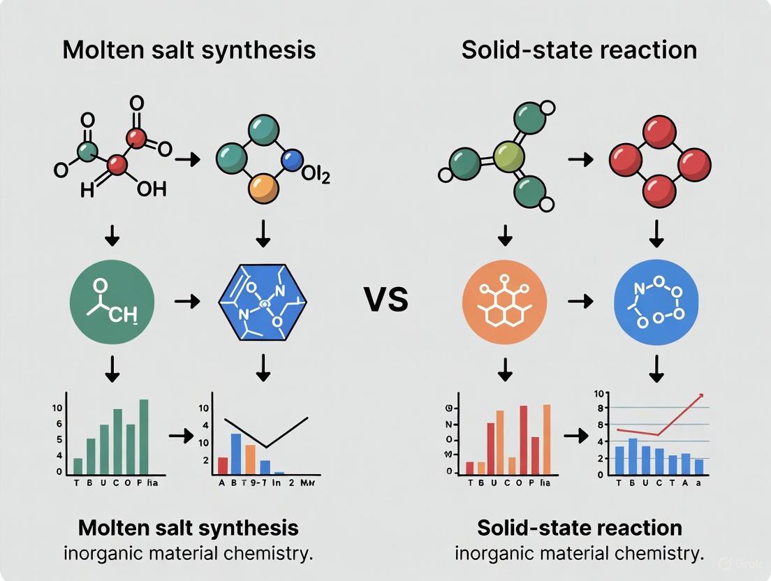
This article provides a systematic comparison between molten salt synthesis (MSS) and conventional solid-state reaction for researchers and scientists developing advanced materials.
Molten Salt Synthesis vs Solid-State Reaction: A Comprehensive Guide for Advanced Material Fabrication
Abstract
This article provides a systematic comparison between molten salt synthesis (MSS) and conventional solid-state reaction for researchers and scientists developing advanced materials. It explores the foundational principles of both techniques, detailing their specific methodological approaches and applications in creating high-performance materials for energy storage, catalysis, and electronics. The content addresses key challenges and optimization strategies for each method and offers a rigorous, evidence-based validation of their relative advantages, limitations, and ideal use cases to inform material selection and process design.
Understanding the Core Principles: Molten Salt and Solid-State Reaction Mechanisms
The synthesis of inorganic solid materials is a cornerstone of modern materials science and chemistry, enabling the development of products ranging from battery cathodes to advanced ceramics. Among the various fabrication methods, solid-state reaction and molten salt synthesis represent two fundamentally different approaches with distinct mechanisms, advantages, and limitations. Solid-state reaction is the most widely used method for preparing polycrystalline solids from mixtures of solid starting materials, requiring high temperatures to facilitate diffusion between solid reactants [1] [2]. In contrast, molten salt synthesis utilizes a molten salt as a reaction medium to prepare complex oxides from their constituent materials at lower temperatures through enhanced ion mobility in the liquid phase [3] [4]. This article provides a comprehensive technical overview of both techniques, including detailed protocols, comparative analysis, and essential reagent solutions, framed within the context of advanced materials research.
Fundamental Principles and Comparative Analysis
Core Mechanisms and Characteristics
Solid-state reaction is a direct reaction between solid precursors where the reaction rate is controlled by solid-state diffusion. Since solids do not react appreciably at room temperature, reactions typically require heating to 1000-1500°C to achieve sufficient atomic diffusion for product formation [1] [2]. The process is governed by factors including reaction conditions, structural properties of reactants, surface area, reactivity, and thermodynamic free energy changes [1].
Molten salt synthesis employs a molten salt solvent (e.g., chlorides, sulfates) that facilitates reactions at lower temperatures (typically 500-1000°C) by providing a liquid medium that enhances ion mobility and reaction rates [3] [5] [4]. The molten salt acts as a solvent where reactants can dissolve and react, precipitating as the desired product phase. This method significantly improves compositional homogeneity and enables morphology control of the resulting powders [5] [6].
Quantitative Technical Comparison
Table 1: Comparative analysis of solid-state reaction versus molten salt synthesis
| Parameter | Solid-State Reaction | Molten Salt Synthesis |
|---|---|---|
| Typical Temperature Range | 1000-1500°C [1] [2] | 500-1000°C (e.g., 650°C for NaCl-KCl) [7] [4] |
| Reaction Medium | Solid-solid interface [1] [2] | Molten salt (liquid phase) [3] [4] |
| Mixing Efficiency | Limited by solid-solid contact; requires extensive grinding [1] [8] | Enhanced by liquid medium; reduces need for intensive mixing [5] [6] |
| Typical Purity | Varies with precursors; often contains impurities | High purity (>96% demonstrated for MAX phases) [7] |
| Particle Morphology Control | Limited [2] | Excellent control of size and shape [3] [5] |
| Compositional Homogeneity | Can be inhomogeneous; requires repeated grinding/heating [2] | High homogeneity due to enhanced diffusion [5] [6] |
| Capital Cost | Moderate (requires high-temperature furnaces) [1] | Low to moderate (simpler instrumentation) [5] |
| Environmental Considerations | Generally clean; may involve volatile components | Green chemistry approach; minimal waste [5] |
| Scalability | Excellent for large-scale production [2] | Highly scalable; easy to implement industrially [5] [4] |
Experimental Protocols
Protocol for Solid-State Reaction Synthesis
The following protocol outlines the standard procedure for preparing polycrystalline solids via solid-state reaction, adaptable for various oxide materials [1] [2] [8]:
Reagent Preparation:
- Select appropriate solid reactants (oxides, carbonates) of high purity (>99%).
- Dry reagents thoroughly in an oven at 100-150°C for several hours to remove absorbed moisture.
Weighing and Mixing:
- Weigh reactants in stoichiometric proportions using an analytical balance.
- For manual mixing of small quantities (<20g), use an agate mortar and pestle.
- Add a volatile organic liquid (acetone or alcohol) to form a paste and mix thoroughly for 10-15 minutes until the liquid evaporates completely [1].
- For larger batches (>20g), use mechanical mixing with a ball mill for several hours.
Container Selection:
Heat Treatment:
- Transfer the mixed powder to the selected container.
- For improved contact between reactant grains, pelletize the powder using a uniaxial press [1] [8].
- Heat in a furnace with an appropriate temperature program:
- Typical heating rate: 2-5°C/min to target temperature (1000-1500°C)
- Dwell time: 4-24 hours at maximum temperature
- Cooling rate: 1-5°C/min to room temperature
- For some materials, repeated grinding and heating cycles may be necessary to improve homogeneity [2].
Product Characterization:
Protocol for Molten Salt Synthesis
This protocol details the molten salt synthesis of complex metal oxide nanoparticles, using lanthanum hafnium oxide (La₂Hf₂O₇) as a representative example [5]:
Salt Selection and Preparation:
Precursor Preparation (for La₂Hf₂O₇ example) [5]:
- Dissolve 2.165 g La(NO₃)₃·6H₂O and 2.0476 g HfOCl₂·8H₂O in 200 mL distilled water with stirring (300 rpm)
- Prepare diluted ammonia solution (3.0%) by adding 20 mL concentrated NH₄OH to 180 mL distilled water
- Titrate the metal solution with diluted ammonia dropwise over 2 hours until precipitate forms
- Age the precipitate overnight, then wash with distilled water until supernatant reaches neutral pH
- Separate the precipitate (La(OH)₃·HfO(OH)₂·nH₂O) via vacuum filtration using coarse porosity filter paper (40-60 µm)
Reaction Mixture Preparation:
Heat Treatment:
Post-Synthesis Processing:
- Cool the reacted mass to room temperature
- Wash the product repeatedly with distilled water or appropriate solvent to remove salt
- Dry the final powder at 80-100°C
- Characterize using XRD, SEM, and other techniques
Workflow Visualization
Synthesis Methodology Decision Tree
The Scientist's Toolkit: Essential Research Reagent Solutions
Successful implementation of either synthesis methodology requires careful selection of reagents and materials. The following table outlines essential research reagent solutions for both techniques:
Table 2: Essential research reagents and materials for solid-state and molten salt synthesis
| Reagent/Material | Function | Application Examples | Technical Notes |
|---|---|---|---|
| Oxide Precursors (TiO₂, Fe₂O₃, Al₂O₃) | Primary reactants for oxide formation | Solid-state synthesis of ceramics, ferrites | High purity (>99.9%), fine particle size (0.5-5 µm) enhances reactivity [7] [2] |
| Carbonate Precursors (Li₂CO₃, CaCO₃, Na₂CO₃) | Source of alkali/alkaline earth metals | Solid-state synthesis of battery materials (NMC) [6] | Decompose during heating; stoichiometry adjustments may be needed due to volatility [4] |
| Chloride Salts (NaCl, KCl, NaCl-KCl eutectic) | Molten salt medium | MSS of MAX phases (Ti₃AlC₂), oxides [7] [4] | Low melting point (650°C for eutectic), high water solubility, inexpensive [7] [4] |
| Sulfate Salts (Na₂SO₄, K₂SO₄) | Molten salt flux | MSS of rock-salt precursors for NMC cathode [6] | Higher melting points; effective for high-temperature MSS |
| Platinum Crucibles | Reaction containers | High-temperature reactions for both methods | Chemically inert but expensive; alternative: alumina crucibles for compatible systems [1] [4] |
| Ammonium Hydroxide (NH₄OH) | Precipitation agent | MSS precursor preparation (e.g., coprecipitation) [5] | Concentration controls particle size in MSS (0.75-7.5%) [5] |
| Agate Mortar and Pestle | Mixing and grinding | Solid-state reactant mixing | Manual mixing for small batches (<20g); mechanical milling for larger quantities [1] |
Advanced Applications and Recent Developments
Molten Salt Synthesis Innovations
Recent advances in molten salt synthesis have demonstrated its versatility for preparing diverse materials with controlled morphologies. The method has successfully produced MAX phases (Ti₃AlC₂, Ti₃SiC₂, etc.) with high purity (>96%) using a dynamic sealing approach in air, overcoming the traditional requirement for inert atmospheres [7]. This innovation significantly reduces complexity and production costs while maintaining excellent powder characteristics. Additionally, MSS has been applied to synthesize rock-salt oxide precursors for NMC622 cathode materials, where the molten salt medium enhances compositional homogeneity and reduces the need for intensive grinding [6]. The method also enables morphology control, producing nanoparticles with specific shapes including nanospheres, nanoflakes, nanoplates, and nanorods by adjusting synthesis parameters [5].
Solid-State Reaction Advancements
Solid-state reactions continue to evolve, particularly in energy storage materials. Recent work has demonstrated the synthesis of hollow-structured LiNi₀.₅Mn₁.₅O₄ (LNMO) cathode materials through impregnation and solid-state reaction, utilizing phenomena analogous to the Kirkendall effect where differential diffusion rates of metal and oxygen atoms create hollow cavities [2]. These structures provide short Li⁺ diffusion paths and accommodate volume changes during cycling, resulting in excellent rate capability and cycling stability. The method has also been optimized for producing LFP/C composites with controlled particle sizes and carbon coating through surfactant-assisted solid-state reactions, demonstrating how precursor treatments can significantly influence final electrochemical performance [2].
Solid-state reaction and molten salt synthesis represent complementary approaches for inorganic material synthesis, each with distinct advantages for specific applications. Solid-state reaction offers simplicity and proven scalability for traditional ceramic and battery materials but requires high temperatures and extensive processing to achieve homogeneity. Molten salt synthesis provides superior control over particle morphology, enhanced compositional homogeneity, and lower processing temperatures, though it requires additional steps for salt removal. The choice between methods depends on specific material requirements, including desired particle characteristics, purity needs, and economic considerations. Recent innovations in both techniques continue to expand their capabilities, addressing challenges in energy storage, electronic materials, and advanced ceramics development. As materials requirements become increasingly demanding, hybrid approaches that leverage the advantages of both methods may offer promising pathways for future materials synthesis.
Molten salts, defined as inorganic salts heated beyond their melting points, create a unique liquid environment for chemical synthesis that is fundamentally different from conventional molecular solvents like water or organic liquids. This high-temperature ionic medium consists of a pool of dissociated cations and anions, offering a powerful combination of high ionic strength, low vapor pressure, and exceptional thermal stability that makes it ideal for facilitating reactions at temperatures typically ranging from 100°C to over 1000°C [3] [5]. Within the broader context of synthesis methodologies, molten salt synthesis (MSS) occupies a crucial position between traditional solid-state reactions, which often suffer from slow diffusion rates and high energy demands, and aqueous/organic solution-phase chemistry, which is limited by solvent boiling points and molecular solvation capabilities [9] [3]. The solvent-mediated pathway in molten salts enables the synthesis of a wide range of advanced materials, from metal oxide nanomaterials to two-dimensional carbides, through mechanisms that enhance reactant mobility, modify reaction pathways, and ultimately control the structure and properties of the final products [9] [10].
The fundamental distinction between molten salt synthesis and conventional solid-state reactions lies in the diffusion kinetics and reaction homogeneity. In solid-state reactions, the chemical reactivity is severely limited by the large diffusion lengths and slow solid-state diffusion of reacting constituents, often resulting in incomplete reactions, irregular morphology, and the need for excessively high temperatures [3]. In contrast, the liquid environment provided by molten salts facilitates fast movement of reactants through convection and diffusion, significantly increasing reaction rates while simultaneously lowering the required synthesis temperature [3] [5]. This solvent-mediated pathway represents a paradigm shift in materials synthesis, enabling the creation of phases and morphologies that are difficult or impossible to achieve through either purely solid-state or conventional solution-based routes.
Fundamental Mechanisms of the Solvent-Mediated Pathway
Physicochemical Principles
The remarkable effectiveness of molten salts as reaction media stems from several interconnected physicochemical principles that govern the solvent-mediated pathway. First, the strong polarizing force generated by the ionic melt plays a crucial role in facilitating chemical reactions. Unlike molecular solvents that may struggle to solvate certain inorganic precursors, the intense electric fields created by molten salt ions can effectively destabilize metal ions and disrupt covalent bonds, making reactants more susceptible to chemical transformation [3]. This polarizing environment is particularly effective for dissolving reactants that are challenging to solubilize in ordinary solvents, thereby expanding the range of viable precursors for materials synthesis [9].
Second, molten salts provide a liquid environment with spatial confinement effects that promote high dispersion of reactants and products throughout the reaction process [9]. The high viscosity and ionic strength of molten salt media prevent the uncontrolled aggregation of growing particles, leading to more uniform nucleation and growth kinetics [5]. This spatial confinement, combined with the enhanced mobility in the liquid phase, enables the design and synthesis of materials with well-defined nanostructures that would be difficult to achieve through other methods [9]. The combination of these factors—strong polarization, spatial confinement, and enhanced diffusion—creates a unique synthetic environment where both dissolution-precipitation and direct transformation mechanisms can operate with exceptional efficiency.
Comparative Analysis: Molten Salt vs. Solid-State Pathways
The fundamental differences between molten salt-mediated pathways and conventional solid-state reactions can be visualized through their distinct mechanistic routes, as illustrated below.
The mechanistic differences between these pathways lead to distinct practical outcomes in materials synthesis. The solvent-mediated pathway in molten salts enables lower processing temperatures, with typical reactions occurring several hundred degrees Celsius below comparable solid-state reactions [3] [5]. For instance, complex metal oxides that require temperatures above 1200°C in solid-state methods can often be synthesized at 600-900°C in molten salt media [5]. Additionally, the product morphology differs significantly between the two approaches. Solid-state reactions typically yield irregular, agglomerated particles with broad size distributions, while molten salt synthesis produces well-defined, discrete particles with controlled shapes and narrow size distributions due to the homogeneous liquid environment and spatial confinement effects [9] [5].
Table 1: Quantitative Comparison of Reaction Parameters and Outcomes
| Parameter | Solid-State Pathway | Molten Salt-Mediated Pathway | Reference |
|---|---|---|---|
| Typical Reaction Temperature | 1000-1400°C | 600-900°C | [3] [5] |
| Diffusion Distance | Limited to solid-solid contact points | Throughout liquid medium | [3] |
| Reaction Homogeneity | Low (heterogeneous) | High (homogeneous) | [9] |
| Product Morphology Control | Limited | High (nanospheres, nanorods, nanoflakes) | [5] |
| Particle Agglomeration | Severe | Minimal | [5] |
| Scalability | Challenging with consistency | Excellent with high reproducibility | [9] [5] |
Key Applications and Experimental Evidence
Synthesis of Metal Oxide Nanomaterials
The solvent-mediated pathway in molten salts has proven particularly valuable for the synthesis of metal oxide nanomaterials with controlled compositions and morphologies. The process enables the creation of both simple binary oxides and complex multi-metal oxides with exceptional phase purity and crystallinity. A prominent example is the synthesis of pyrochlore lanthanum hafnium oxide (La₂Hf₂O₇) nanoparticles, which demonstrates the advantages of the molten salt approach for preparing complex oxides with refractory nature [5]. The typical protocol involves a two-step process where a single-source complex precursor is first prepared through coprecipitation, followed by reaction in a nitrate-based molten salt medium (NaNO₃:KNO₃ = 1:1 molar ratio) at 650°C for 6 hours [5]. This method yields highly crystalline, non-agglomerated nanoparticles with uniform size distribution, overcoming the limitations of conventional solid-state reactions that would require significantly higher temperatures and still produce irregular morphologies.
The versatility of the molten salt-mediated pathway extends to numerous other complex metal oxide structures, including perovskites (ABO₃), spinels (AB₂O₄), and various orthorhombic structures [3] [5]. The ability to control particle size, shape, and crystallinity through simple manipulation of synthesis parameters such as salt composition, temperature, duration, and pH represents a significant advantage over solid-state methods [5]. For instance, by varying the concentration of ammonium hydroxide solution used in the precursor preparation stage, researchers can systematically control the final particle size of La₂Hf₂O₇ nanoparticles, enabling precise exploration of size-dependent properties [5]. This level of control is exceptionally difficult to achieve through conventional solid-state reactions where particle size is typically determined by grinding and milling processes that offer poor uniformity.
Synthesis and Etching of Two-Dimensional Materials
Beyond oxide synthesis, the solvent-mediated pathway in molten salts has enabled breakthroughs in the preparation and processing of two-dimensional materials, particularly MXenes. Traditional MXene synthesis relies on hazardous hydrofluoric acid (HF) to etch the A-element layer from MAX phase precursors, posing significant safety and environmental concerns [10]. The molten salt-mediated pathway offers a safer, more controllable alternative using Lewis acid molten salts such as ZnCl₂, CuCl₂, or NiCl₂ as etchants [10]. In this approach, the molten salt acts as both the reaction medium and the etching agent, facilitating the selective removal of the A-layer through redox reactions while simultaneously providing a liquid environment that enables the formation of well-defined two-dimensional structures.
The experimental protocol for MXene synthesis via molten salt etching typically involves mixing the MAX phase precursor with an appropriate metal halide salt (e.g., ZnCl₂) and heating the mixture above the salt's melting point (approximately 300-500°C) for several hours under inert atmosphere [10]. The process can be represented as a two-stage mechanism where the A-element is first removed from the MAX phase through oxidation by the metal halide, followed by intercalation and exfoliation to yield the final MXene product. This solvent-mediated approach not only eliminates the need for hazardous HF but also provides superior control over surface terminations, enabling the introduction of chloride, bromide, or other functional groups that significantly influence the electrical and catalytic properties of the resulting MXenes [10]. For example, Nb₂CTx MXenes prepared via molten salt etching exhibited electrical conductivity values ranging from 25 S cm⁻¹ to 345 S cm⁻¹ depending on the surface termination (O, NH, S, Se, Cl), demonstrating the critical role of surface chemistry in determining material properties [10].
Enhanced Carbon Capture and Catalytic Conversion
The solvent-mediated pathway in molten salts also finds application in energy and environmental technologies, particularly in integrated carbon capture and utilization processes. Recent research has demonstrated that NaCl-CaCl₂ molten salt systems significantly enhance the performance of CaO-based CO₂ capture and subsequent conversion via the reverse water gas shift (RWGS) reaction [11]. In this application, the molten salt creates a liquid environment that disrupts the crystalline structure of CaO, facilitating CO₂ capture through adsorbed oxygen sites rather than conventional lattice oxygen pathways [11]. This altered mechanism leads to dramatically improved performance, with the system achieving 56.99% CO₂ conversion at 650°C, accompanied by an average CO₂ capture rate of 0.64 mmol g⁻¹ min⁻¹ and CO generation rate of 0.23 mmol g⁻¹ min⁻¹ [11].
The experimental protocol for this application involves preparing a mixture of CaO with NaCl-CaCl₂ salts (typically in specific eutectic compositions) and loading the mixture into a fixed-bed reactor system [11]. The CO₂ capture and conversion process typically cycles between carbonation steps (where CO₂ is captured from a gas stream) and reduction steps (where the captured carbon is converted to CO via the RWGS reaction). Characterization techniques including TG-DSC, XPS, in-situ DRIFTS, and in-situ Raman spectroscopy have confirmed that the eutectic melting behavior of the salts is the main factor enhancing CO₂ capture capacity and CO generation rates compared to CaO alone [11]. This application highlights how the solvent-mediated pathway in molten salts can fundamentally alter reaction mechanisms to enhance performance in critical energy technologies.
Table 2: Performance Metrics of Molten Salt-Enhanced Processes Across Applications
| Application | Key Performance Metrics | Molten Salt System | Advantage Over Alternative Methods | Reference |
|---|---|---|---|---|
| Metal Oxide Synthesis | Highly crystalline, non-agglomerated NPs | NaNO₃:KNO₃ (1:1) | Lower temperature (650°C vs. >1200°C), better morphology control | [5] |
| MXene Synthesis | Controlled surface terminations, conductivity 25-345 S cm⁻¹ | ZnCl₂, CuCl₂, NiCl₂ | HF-free etching, tunable surface chemistry | [10] |
| CO₂ Capture & Conversion | 56.99% CO₂ conversion, 0.64 mmol g⁻¹ min⁻¹ capture rate | NaCl-CaCl₂ | Enhanced capacity vs. CaO alone, lower operating temperature | [11] |
| Solid-State Emitting Carbon Dots | 90% quantum yield, kilogram-scale production | NaCl-KCl-ZnCl₂ | Low temperature (100-142°C), short reaction time (10 min) | [12] |
Essential Research Reagents and Materials
The successful implementation of molten salt-mediated synthesis requires careful selection of salts and precursors based on their physicochemical properties and compatibility with the desired reaction. The table below summarizes key reagents and their functions in various molten salt applications.
Table 3: Essential Research Reagents for Molten Salt-Mediated Synthesis
| Reagent Category | Specific Examples | Key Properties & Functions | Typical Applications |
|---|---|---|---|
| Alkali Metal Nitrates | NaNO₃, KNO₃, LiNO₃ | Low melting point (~250-350°C for mixtures), oxidizing environment, good oxide ion solubility | Metal oxide synthesis, particularly perovskites and complex oxides [3] [5] |
| Chloride Salts | NaCl, KCl, ZnCl₂, CuCl₂ | Wide temperature range (300-1000°C), Lewis acidic character, versatile coordination chemistry | MXene etching, catalyst synthesis, nanoparticle preparation [12] [9] [10] |
| Eutectic Mixtures | NaNO₃:KNO₃, NaCl:CaCl₂, NaCl:KCl:ZnCl₂ | Depression of melting point, tunable physicochemical properties, enhanced ionic mobility | Low-temperature synthesis, carbon dot preparation, enhanced catalysis [11] [12] [5] |
| Metal Oxide Precursors | Metal nitrates, chlorides, hydroxides, carbonates | High solubility in molten salts, appropriate decomposition behavior, compatibility with salt chemistry | Wide range of oxide nanomaterials including binary and complex oxides [3] [5] |
| MAX Phase Precursors | Ti₃AlC₂, Ti₂AlC, Mo₂GaC, V₂AlC | Layered structure with etchable A-element, stability at reaction temperatures | MXene synthesis through selective etching [10] |
The selection of appropriate molten salt media depends critically on several factors including melting temperature, solubility parameters, chemical compatibility with precursors, and ease of removal after reaction. For oxide synthesis, nitrate salts are particularly advantageous due to their relatively low melting points and oxidizing nature, which facilitates oxide formation [3] [5]. Chloride-based salts offer wider temperature ranges and greater diversity in Lewis acidity, making them suitable for etching applications and the synthesis of non-oxide materials [9] [10]. Eutectic mixtures, which combine two or more salts to achieve melting points lower than those of the individual components, are especially valuable for low-temperature synthesis and for creating specific chemical environments tailored to particular reactions [11] [12].
Detailed Experimental Protocols
Protocol 1: Synthesis of Metal Oxide Nanoparticles
The following detailed protocol for the synthesis of lanthanum hafnium oxide (La₂Hf₂O₇) nanoparticles illustrates the general principles of molten salt-mediated synthesis for complex metal oxides [5].
Materials and Equipment:
- Lanthanum nitrate hexahydrate (La(NO₃)₃·6H₂O)
- Hafnium dichloride oxide octahydrate (HfOCl₂·8H₂O)
- Ammonium hydroxide solution (NH₄OH, 28-30%)
- Sodium nitrate (NaNO₃) and potassium nitrate (KNO₃)
- Distilled water
- Standard laboratory glassware (beakers, burette, stirring hotplate)
- Vacuum filtration apparatus
- High-temperature furnace capable of reaching at least 700°C
- Porcelain crucibles
Procedure:
- Preparation of Single-Source Complex Precursor:
- Dissolve 2.165 g of La(NO₃)₃·6H₂O and 2.0476 g of HfOCl₂·8H₂O in 200 mL of distilled water in a 500 mL beaker with continuous stirring at 300 rpm.
- Prepare a diluted ammonia solution (3.0% typically) by adding 20 mL of concentrated NH₄OH to 180 mL of distilled water.
- Add the diluted ammonia solution dropwise to the stirring precursor solution over a period of 2 hours using a burette.
- Allow the resulting precipitate to age overnight, then wash with distilled water until the supernatant reaches neutral pH (typically 5-8 washes).
- Recover the precipitate (La(OH)₃·HfO(OH)₂·nH₂O) via vacuum filtration using coarse porosity filter paper (40-60 µm) and dry at 80°C for 12 hours.
Molten Salt Reaction:
- Thoroughly mix the dried precursor with a nitrate salt mixture (NaNO₃:KNO₃ in 1:1 molar ratio) using a 1:10 to 1:20 precursor-to-salt mass ratio.
- Transfer the mixture to a porcelain crucible and heat in a furnace at 650°C for 6 hours with a heating rate of 5°C/min.
- After reaction, allow the crucible to cool naturally to room temperature.
Product Recovery and Purification:
- Leach the cooled product with copious distilled water to dissolve the solidified salt matrix.
- Separate the insoluble La₂Hf₂O₇ nanoparticles by centrifugation or filtration.
- Wash the recovered nanoparticles repeatedly with distilled water until no salt residue is detected (verified by silver nitrate test for chloride ions).
- Dry the purified nanoparticles at 80°C for 12 hours before characterization.
Critical Parameters and Troubleshooting:
- The concentration of ammonia solution during precursor preparation significantly influences final particle size; lower concentrations (0.75-1.5%) yield smaller particles, while higher concentrations (6.0-7.5%) produce larger particles [5].
- Incomplete washing after precipitation may lead to incorporated impurities that affect the final product composition.
- Insufficient salt quantity or improper mixing may result in particle agglomeration due to reduced spatial confinement.
- Rapid cooling after reaction may cause thermal stress and introduce defects in the crystalline structure.
Protocol 2: Molten Salt Etching of MXenes
This protocol describes the synthesis of MXenes from MAX phase precursors using Lewis acid molten salt etching, providing a safer alternative to traditional HF-based methods [10].
Materials and Equipment:
- MAX phase precursor (e.g., Ti₃AlC₂, Ti₂AlC, V₂AlC)
- Anhydrous metal chloride salts (e.g., ZnCl₂, CuCl₂, NiCl₂)
- Argon or nitrogen gas supply for inert atmosphere
- Glassy carbon crucible or alumina crucible
- Tube furnace with gas flow controls
- Centrifuge and vacuum filtration equipment
- Organic solvents (e.g., ethanol, isopropanol) for washing
Procedure:
- Reaction Setup:
- Thoroughly mix MAX phase powder with excess metal chloride salt (typically 1:5 to 1:20 mass ratio) in a glove box under inert atmosphere to prevent moisture absorption.
- Transfer the mixture to an appropriate crucible (glassy carbon or alumina recommended for corrosion resistance).
- Place the crucible in a tube furnace and seal the system.
Etching Reaction:
- Purge the reaction system with inert gas (Ar or N₂) for at least 30 minutes to remove oxygen and moisture.
- Heat the mixture to the desired reaction temperature (300-500°C depending on the salt system) with a heating rate of 3-5°C/min.
- Maintain at the target temperature for 1-12 hours to complete the etching process.
- Cool naturally to room temperature under continued inert gas flow.
Product Recovery and Delamination:
- Transfer the cooled reaction product to a beaker and add distilled water to dissolve the excess salt.
- Separate the MXene product by centrifugation and wash repeatedly with water and ethanol to remove residual salts.
- For delamination, subject the MXene to intercalation using appropriate agents (e.g., tetraalkylammonium hydroxides, DMSO) followed by mild sonication.
- Recover the delaminated MXene as a colloidal suspension via centrifugation.
Critical Parameters and Troubleshooting:
- The selection of metal chloride etchant depends on the MAX phase composition; the redox potential must favor oxidation of the A-element [10].
- Moisture contamination must be rigorously avoided as it can lead to oxide formation and compromised MXene quality.
- Over-etching or excessive reaction times may damage the MXene structure and reduce yield.
- Incomplete washing may leave residual salts that affect subsequent applications, particularly in electrochemical systems.
The workflow for MXene synthesis via molten salt etching, illustrating the key steps and their outcomes, can be visualized as follows:
Advanced Applications and Emerging Directions
Monitoring and Characterization in Molten Salt Systems
The development of advanced in situ monitoring techniques represents a crucial frontier in understanding and optimizing the solvent-mediated pathway in molten salts. Traditional ex situ characterization methods provide limited insight into the dynamic processes occurring within the high-temperature ionic liquid environment. Recent advances in analytical techniques have enabled real-time monitoring of chemical changes in molten salt systems, offering unprecedented insights into reaction mechanisms and degradation processes [13]. For instance, researchers at Oak Ridge National Laboratory have demonstrated the application of laser-induced breakdown spectroscopy (LIBS) for tracking chemical changes in molten salts by creating a microplasma in a molten salt aerosol stream and detecting impurities within that stream [13]. This technique allows for elemental fingerprinting of the sample in less than a second, providing rapid feedback on system composition and potential corrosive species.
Complementary in situ techniques including synchrotron-based X-ray diffraction and X-ray absorption spectroscopy have been developed to study reaction mechanisms directly in molten salt environments [14]. These approaches have revealed unconventional one-dimensional corrosion modes and increased vacancy concentrations in structural materials, information that is critical for designing corrosion-resistant alloys for molten salt reactor applications [15]. Similarly, radionuclide tracing techniques have enabled real-time monitoring of corrosion product transport in operational loops, providing valuable data on the dynamic interactions at the salt-alloy interface [15]. The integration of these advanced characterization methods with computational modeling and machine learning approaches promises to accelerate the understanding and optimization of molten salt-mediated processes across applications from nuclear energy to materials synthesis [15].
Corrosion Science and Mitigation Strategies
As molten salt technologies advance, understanding and mitigating corrosion in these aggressive environments has emerged as a critical research direction. The absence of a passivating oxide layer in molten salts creates conditions for rapid material degradation, particularly in high-temperature applications such as molten salt reactors (MSRs) [15]. Recent research has significantly advanced the molecular-level understanding of corrosion mechanisms, revealing that conventional models based solely on thermodynamic nobility are insufficient to predict material performance in these environments [15]. For example, high-throughput experiments combined with machine learning have shed light on the role of alloy composition and elemental mobility in determining corrosion resistance, highlighting the complex interplay between thermodynamic and kinetic factors [15].
Several promising mitigation strategies have emerged from these fundamental studies. Redox potential control through the addition of specific buffering agents has proven effective in mitigating corrosive attacks by maintaining the salt chemistry within a window that minimizes aggressive dissolution of alloy components [15]. Additionally, materials design approaches informed by advanced characterization and computational modeling have led to the development of alloys with improved resistance to corrosion in molten salt environments [15]. For instance, studies have demonstrated that proton irradiation can paradoxically decelerate intergranular corrosion by promoting the replenishment of alloy constituents at critical interfaces, challenging conventional assumptions about irradiation effects [15]. These advances in corrosion science not only benefit nuclear energy applications but also inform the design of reactors and containers for materials synthesis using molten salt media, enabling longer operational lifetimes and improved process consistency.
Future Perspectives and Research Needs
The field of molten salt-mediated synthesis continues to evolve with several emerging trends and research needs. The integration of machine learning and high-throughput experimentation represents a particularly promising direction for accelerating the discovery and optimization of molten salt systems [12] [15]. For example, machine learning approaches have been successfully employed to optimize the synthesis of solid-state emitting carbon dots in molten salts, achieving unprecedented quantum yields of ~99.86% by identifying optimal reaction conditions that would be difficult to discover through traditional experimentation alone [12]. Similar approaches could be extended to other materials systems, potentially revolutionizing the development of molten salt processes.
The scaling of molten salt synthesis from laboratory to industrial scale presents both challenges and opportunities. While the inherent scalability of molten salt methods has been demonstrated for several material systems [9] [5], further research is needed to develop continuous flow processes that could enable truly large-scale production. Additionally, the recycling and reuse of molten salts represent an important sustainability consideration that warrants further investigation [9]. The development of closed-loop salt recycling processes would improve the economic viability and environmental profile of molten salt synthesis methods. Finally, the exploration of new salt compositions and combinations, including deep eutectic solvents and ionic liquids with extended temperature ranges, may open new possibilities for materials synthesis and processing that combine the advantages of low-temperature solution chemistry with high-temperature solid-state reactions.
Solid-state diffusion is a fundamental process in which atoms, ions, or molecules move within a solid material, driven by concentration gradients, temperature, or other external forces [16]. Unlike gaseous or liquid states where particle movement is rapid and largely unrestricted, atomic migration in solids occurs despite atoms being firmly fixed in a crystalline or amorphous structure, constrained by solid bonds [16]. This phenomenon is governed by thermal vibrations that provide atoms with minimal energy to move from their equilibrium positions, enabling significant material transformations over time [16].
In the context of materials synthesis, solid-state diffusion represents one of the two primary pathways for creating complex ceramic materials, standing in direct contrast to molten salt synthesis methods. Where molten salt synthesis employs a liquid solvent medium to enhance reactant mobility and reduce reaction temperatures, the solid-state diffusion pathway relies exclusively on atomic migration through crystalline lattices without any solvent participation [4] [3]. This fundamental distinction creates significant differences in reaction kinetics, microstructural development, and final material properties that researchers must consider when selecting synthesis routes for specific applications.
The importance of solid-state diffusion extends across numerous industrial and natural processes, including sintering of ceramics, creation of alloys, hardening of metals, and the formation of complex oxide materials [16]. In materials research and drug development, understanding these atomic-scale migration processes enables precise control over material properties including porosity, crystallinity, and surface characteristics - all critical factors in pharmaceutical applications ranging from drug delivery systems to excipient design.
Fundamental Mechanisms of Atomic Migration
In crystalline structures, atoms migrate primarily through two well-established mechanisms, each with distinct characteristics and requirements for atomic movement through the crystal lattice.
Vacancy Diffusion Mechanism
The vacancy mechanism, also known as substitutional diffusion, involves atoms moving to occupy empty lattice sites left by other atoms in the crystal structure [16]. This process requires the presence of vacancies or defects in the equilibrium crystal structure, which become more numerous as temperature increases. For an atom to successfully migrate via this mechanism, it must possess sufficient energy from thermal vibration to break bonds with neighboring atoms and move into an adjacent vacancy [16]. The necessary energy is the sum of the energy required to form the vacancy and the energy needed to move the atom through the crystal lattice [16]. In metals with high melting points, where binding energies between atoms are stronger, more activation energy is required for this diffusion mechanism to occur [16]. This mechanism dominates in systems where the diffusing atoms have similar sizes to the host lattice atoms, such as copper atoms diffusing in a copper crystal structure or in solid solutions where atomic size and binding energy differences influence diffusion rates [16].
Interstitial Diffusion Mechanism
The interstitial diffusion mechanism occurs when smaller atoms move through the gaps between larger atoms in the crystal lattice without displacing any matrix atoms [16]. For this mechanism to operate effectively, the diffusing atoms must be relatively small compared to those forming the crystal lattice [16]. Elements such as hydrogen, oxygen, nitrogen, boron, and carbon can diffuse interstitially in most metallic crystal lattices due to their small atomic radii [16]. The migration path involves atoms moving from one interstice to an adjacent one without permanently distorting the crystal structure. This mechanism typically proceeds at faster rates than vacancy diffusion due to the lower energy barriers involved, as interstitial atoms do not need to break as many chemical bonds during migration.
Table 1: Comparison of Solid-State Diffusion Mechanisms
| Characteristic | Vacancy Diffusion | Interstitial Diffusion |
|---|---|---|
| Atomic Mechanism | Atoms exchange with vacant lattice sites | Small atoms move between interstitial spaces |
| Atom Size Requirement | Similar size to lattice atoms | Significantly smaller than lattice atoms |
| Energy Requirement | Higher (must break multiple bonds) | Lower (fewer bonds to break) |
| Diffusion Rate | Generally slower | Generally faster |
| Common Examples | Copper in copper, alloy formation | Carbon in iron, hydrogen in metals |
| Temperature Dependence | Strong temperature dependence | Strong temperature dependence |
Mathematical Framework: Fick's Laws of Diffusion
The quantitative analysis of solid-state diffusion is governed by Fick's Laws, which provide a mathematical framework for describing diffusion processes under different conditions.
Fick's First Law: Steady-State Diffusion
Fick's First Law describes diffusion under steady-state conditions, where the concentration of atoms at any point in the material does not change with time [16]. This law states that the net flux of atoms is proportional to the concentration gradient, with the mathematical expression:
J = -D(dC/dx) [16]
Where:
- J represents the net flux or current of atoms (atoms/m²·s)
- D is the diffusion coefficient or diffusivity (m²/s)
- dC/dx is the concentration gradient (atoms/m³·m)
- The negative sign indicates that diffusion occurs from regions of higher concentration to lower concentration [16]
Steady-state diffusion conditions are achieved when there is no change in solute concentration over time at any position in the diffusion system. A classic example is hydrogen gas diffusing through a palladium foil, where high hydrogen pressure on one side and low pressure on the other maintain a constant concentration gradient [16].
Fick's Second Law: Non-Steady-State Diffusion
While not explicitly detailed in the search results, Fick's Second Law addresses non-steady-state diffusion where concentrations change with time. This partial differential equation takes the form ∂C/∂t = D(∂²C/∂x²) for one-dimensional diffusion. Non-steady-state conditions are more commonly encountered in practical materials synthesis and processing scenarios, where concentration gradients evolve throughout the diffusion process until equilibrium is approached.
The diffusion coefficient D exhibits strong temperature dependence following an Arrhenius relationship: D = D₀exp(-Q/RT), where D₀ is a pre-exponential factor, Q is the activation energy for diffusion, R is the gas constant, and T is absolute temperature. This relationship explains why diffusion processes accelerate dramatically with increasing temperature, as thermal energy provides atoms with the necessary activation energy to overcome energy barriers to migration.
Diagram 1: Mathematical framework of solid-state diffusion
Experimental Protocols for Studying Solid-State Diffusion
Protocol: Investigation of BaTiO3 Formation via Solid-State Diffusion
Objective: To synthesize barium titanate (BaTiO3) through solid-state reaction between BaCO3 and TiO2 and characterize the diffusion-controlled kinetics and resulting microstructure.
Materials and Equipment:
- Barium carbonate (BaCO3) powder, 99% purity
- Titanium dioxide (TiO2) powder, 99% purity
- Mortar and pestle or ball milling equipment
- Die set and hydraulic press
- High-temperature furnace capable of reaching 1200°C
- Alumina crucibles
- X-ray diffractometer (XRD)
- Scanning electron microscope (SEM)
Procedure:
- Raw Material Preparation: Weigh BaCO3 and TiO2 powders in stoichiometric ratio (1:1 molar ratio). Mix thoroughly using mortar and pestle for 30 minutes or employ ball milling for 2 hours for improved homogeneity.
- Pelletization: Transfer the mixed powder to a die set and compress at 100 MPa using a hydraulic press to form pellets approximately 13mm in diameter and 2-3mm thick. The compaction enhances interparticle contact and reduces diffusion distances.
- Heat Treatment: Place pellets in alumina crucibles and heat in a furnace under air atmosphere. Employ a heating rate of 5°C/min to the target temperature (1000-1200°C) and maintain for 2-8 hours.
- Cooling and Sampling: After the reaction period, cool the samples to room temperature at 3°C/min. Collect samples at different time intervals for kinetic studies if required.
- Characterization: Analyze phase formation using XRD. Examine microstructure and particle size using SEM. Compare with literature data to identify diffusion-controlled characteristics.
Key Observations: Conventional solid-state synthesis of BaTiO3 typically requires temperatures above 1000°C and results in significant particle agglomeration, coarse particle sizes, and poor chemical homogeneity due to the limitations of solid-state diffusion [17]. The microstructure development is directly controlled by diffusion rates, which are influenced by temperature, particle size, and interfacial contact areas.
Protocol: Comparative Analysis of Diffusion-Controlled vs. Solvent-Assisted Synthesis
Objective: To directly compare the solid-state diffusion pathway with molten salt synthesis using the same starting materials (BaCO3 and TiO2) and characterize differences in reaction kinetics, morphology, and particle properties.
Materials and Equipment:
- All materials from Protocol 4.1
- Sodium chloride (NaCl), 99% purity
- Potassium chloride (KCl), 99% purity
- Deionized water
- Centrifuge or filtration equipment
Procedure:
- Sample Preparation: Divide the mixed BaCO3-TiO2 powder into two equal portions.
- Solid-State Reaction: Follow Protocol 4.1 for the first portion.
- Molten Salt Synthesis: For the second portion, mix with NaCl-KCl eutectic mixture (1:1 molar ratio) with salt-to-reactant weight ratio of 1:1. Heat at 800-900°C for 3 hours in covered alumina crucible. After reaction, cool to room temperature, wash with deionized water to remove salts, and dry at 150°C for 2 hours.
- Comparative Characterization: Analyze both sample sets using XRD for phase formation, SEM for morphology, and laser diffraction for particle size distribution.
Expected Results: The molten salt synthesis will demonstrate lower formation temperature (reduced by 200-300°C), more uniform morphology, and decreased particle agglomeration compared to the solid-state diffusion route [17] [3]. This comparison highlights how the liquid phase in molten salt synthesis enhances mass transport and overcomes diffusion limitations inherent in solid-state reactions.
Table 2: Comparative Analysis of Synthesis Methods for BaTiO3
| Parameter | Solid-State Diffusion | Molten Salt Synthesis |
|---|---|---|
| Reaction Temperature | 1000-1200°C [17] | 700-900°C [17] |
| Reaction Time | 2-8 hours | 2-5 hours |
| Particle Morphology | Irregular, agglomerated | Uniform, well-defined shapes [17] |
| Particle Size | 1-10 μm, broad distribution | 50-900 nm, controllable [17] |
| Chemical Homogeneity | Limited by diffusion | Enhanced through liquid phase |
| Key Limitation | Slow diffusion, high temperature | Salt removal required |
| Industrial Scalability | Well-established | Promising, with salt recycling |
The Scientist's Toolkit: Essential Research Reagents and Materials
Table 3: Essential Materials for Solid-State Diffusion Studies
| Reagent/Material | Function/Application | Example Use Cases |
|---|---|---|
| Metal Oxides (TiO2, Fe2O3, Nb2O5) | Reactants for complex oxide formation | BaTiO3, LaFeO3 synthesis [17] [18] |
| Carbonates (BaCO3, SrCO3, CaCO3) | Source of alkaline earth metals | BaTiO3, SrTiO3 formation [17] [19] |
| Alumina Crucibles | High-temperature containers | Withstand temperatures up to 1500°C |
| Hydraulic Press & Die Set | Pellet formation | Enhance interparticle contact |
| High-Temperature Furnace | Heat treatment | Maintain precise temperature profiles |
| XRD Equipment | Phase identification and analysis | Confirm product formation and purity |
| SEM/TEM | Microstructural characterization | Particle size, morphology analysis [17] |
Diagram 2: Solid-state synthesis experimental workflow
Implications for Materials Design and Processing
The fundamental understanding of solid-state diffusion pathways has profound implications for materials design and processing across numerous scientific and industrial domains.
In ceramic materials synthesis, the limitations of solid-state diffusion - including high processing temperatures, slow reaction kinetics, and limited control over microstructure - have motivated the development of alternative approaches like molten salt synthesis [17] [3]. The MSS method addresses these limitations by providing a liquid medium that enhances mass transport, enabling lower processing temperatures (typically reduced by 200-400°C), faster reaction rates, and improved control over particle morphology and size distribution [17] [3] [19]. For example, while solid-state synthesis of BaTiO3 typically requires temperatures above 1000°C and produces irregular, agglomerated particles, molten salt synthesis can achieve the same phase at 700-900°C with controllable particle sizes ranging from 50-900 nm and well-defined morphologies [17].
For pharmaceutical development, understanding solid-state diffusion is crucial for controlling drug polymorphism, stability, and release characteristics. The diffusion-controlled phase transformations in active pharmaceutical ingredients (APIs) and excipients can significantly impact bioavailability and shelf life. Additionally, the principles of solid-state diffusion inform the design of controlled-release formulations where drug diffusion through polymer matrices determines release kinetics.
In energy materials development, solid-state diffusion processes are integral to the performance of battery electrodes, solid oxide fuel cells, and hydrogen storage materials [20] [19]. For instance, in all-solid-state batteries, interfacial diffusion between electrodes and solid electrolytes often limits performance and stability [20]. Similarly, in reversible solid oxide cells (RSOC), oxygen electrode materials like La0.6Sr0.4FeO3-δ (LSF) benefit from nanostructuring approaches that reduce diffusion distances and enhance electrocatalytic activity [19].
The comparative analysis between solid-state diffusion and solvent-assisted synthesis methods provides researchers with a fundamental framework for selecting appropriate synthesis routes based on target material properties, processing constraints, and application requirements. While solid-state reactions remain important for many commercial applications due to their simplicity and scalability, molten salt and other solution-based methods offer superior control for advanced materials where precise morphology, particle size, and phase purity are critical.
Within materials science, the synthesis of inorganic compounds hinges on the careful control of experimental parameters. For solid-state methods, temperature, time, and precursor selection are particularly critical, as they directly influence reaction kinetics, diffusion rates, and ultimately, the phase purity and morphology of the product. This application note provides a detailed comparison of these essential parameters in two prominent synthesis techniques: the conventional solid-state reaction method and the molten salt synthesis (MSS) method. Framed within a broader thesis comparing these routes, this document offers standardized protocols and quantitative data to guide researchers in selecting and optimizing synthesis conditions for their specific material targets.
Comparative Parameter Analysis
The choice between solid-state reaction and molten salt synthesis significantly impacts the required experimental conditions and the characteristics of the final product. The table below summarizes the core differences in how each method approaches the key parameters of temperature, time, and precursor selection.
Table 1: Comparative analysis of essential parameters in solid-state reaction versus molten salt synthesis.
| Parameter | Conventional Solid-State Reaction | Molten Salt Synthesis (MSS) |
|---|---|---|
| Typical Temperature Range | High temperatures (often >1000°C) [21] [3] | Low to moderate temperatures (e.g., 300°C - 900°C) [5] [12] [21] |
| Typical Time Scale | Long durations (several hours to days) [2] | Shorter holding times (e.g., 1 hour to 6 hours) [5] [21] |
| Precursor Selection | Relies on solid-state diffusion; precursors must be finely ground and mixed [2]. | Molten salt acts as solvent; enhances precursor mobility and reaction rate [5] [3]. |
| Particle Morphology Control | Limited control; prone to agglomeration and irregular shapes [2]. | Excellent control; enables nanospheres, nanoflakes, nanorods, etc. [5] [3] |
| Key Advantage | Simplicity and large-scale production [2]. | Lower energy requirement, high crystallinity, and minimal agglomeration [5] [3]. |
| Primary Limitation | Lack of good control over final size and shape [2]. | Requires post-synthesis washing to remove salt [5] [21]. |
Detailed Experimental Protocols
Protocol: Molten Salt Synthesis of La₂Hf₂O₇ Nanoparticles
This protocol outlines the synthesis of highly crystalline, complex metal oxide nanoparticles via the MSS method [5].
Research Reagent Solutions
Table 2: Key reagents for the molten salt synthesis of La₂Hf₂O₇ nanoparticles.
| Reagent | Function/Note |
|---|---|
| Lanthanum Nitrate Hexahydrate (La(NO₃)₃•6H₂O) | Metal cation precursor |
| Hafnium Dichloride Oxide Octahydrate (HfOCl₂•8H₂O) | Metal cation precursor |
| Ammonium Hydroxide Solution (NH₄OH) | Precipitating agent for single-source complex precursor |
| Sodium Nitrate (NaNO₃) & Potassium Nitrate (KNO₃) | Molten salt medium (1:1 molar ratio) |
Step-by-Step Procedure
Preparation of Single-Source Complex Precursor:
- Dissolve 2.165 g of La(NO₃)₃•6H₂O and 2.0476 g of HfOCl₂•8H₂O in 200 mL of distilled water with stirring (300 rpm) for 30 minutes [5].
- Prepare a diluted ammonia solution (e.g., 3.0% by adding 20 mL of concentrated NH₄OH to 180 mL distilled water) [5].
- Add the diluted ammonia solution dropwise to the stirring precursor solution over a period of 2 hours. A cloudy precipitate (La(OH)₃·HfO(OH)₂·nH₂O) will form [5].
- Allow the precipitate to age overnight, then wash with distilled water via centrifugation or decanting until the supernatant reaches a neutral pH [5].
- Recover the precursor via vacuum filtration and dry it [5].
Molten Salt Reaction:
- Combine the single-source complex precursor with a nitrate salt mixture (NaNO₃:KNO₃ in a 1:1 molar ratio). A typical weight ratio of salt to precursor is 3:1 [5] [21].
- Grind the mixture with a mortar and pestle to ensure homogeneity [5].
- Transfer the mixture to a suitable crucible and heat in a furnace at 650°C for 6 hours [5].
Post-Synthesis Processing:
- After cooling to room temperature, the product will be a solid block. Dissolve this block in a 1:1 ethanol-water solution to remove the molten salts [5] [22].
- Wash the recovered powder thoroughly with distilled water via vacuum filtration until no salt residue remains [5].
- Dry the final product (La₂Hf₂O₇ NPs) at 120°C overnight [5].
Protocol: Solid-State Synthesis of LiFePO₄/C (LFP/C) Composites
This protocol describes the synthesis of polycrystalline cathode materials via the solid-state reaction method, highlighting the role of surfactants [2].
Research Reagent Solutions
Table 3: Key reagents for the solid-state synthesis of LFP/C composites.
| Reagent | Function/Note |
|---|---|
| Lithium Hydroxide (LiOH) & Iron Precursors (e.g., Nitrates) | Reactants for LiFePO₄ formation |
| Tween 80 (Surfactant) | Long-chain surfactant to prevent particle growth [2]. |
| Tween 20 (Surfactant) | Shorter-chain surfactant that forms more carbon during pyrolysis [2]. |
Step-by-Step Procedure
Precursor Preparation and Mixing:
- Select appropriate solid precursors (e.g., carbonates, oxides) for Li, Fe, and P [2].
- Weigh precursors in a stoichiometric ratio for the target compound, LiFePO₄.
- Add surfactants (e.g., a combination of Tween 80 and Tween 20 in a 1.5:1 ratio) to control particle size and carbon content [2].
- Mix and grind the solid reactants thoroughly using a ball mill or mortar and pestle to achieve intimate mixing and reduce diffusion path lengths [2].
High-Temperature Calcination:
- Transfer the homogeneous powder mixture to a high-temperature stable crucible.
- Heat the mixture in a furnace under an inert or controlled atmosphere (to prevent oxidation of Fe²⁺) at high temperatures, often exceeding 800°C, for several hours [2].
Post-Synthesis Processing:
- After the reaction, allow the product to cool slowly to room temperature under the same atmosphere.
- The resulting product may be lightly ground again to break up soft agglomerates and sieved to obtain a uniform powder [2].
Parameter Optimization and Workflow
The following diagram illustrates the decision-making workflow and the interconnectedness of the key parameters in both synthesis methods, guiding researchers from target material to final product.
Advanced Considerations
The Impact of Precursor Properties in MSS
The physical and chemical properties of precursors are critical in MSS and can dictate the reaction mechanism and final particle morphology.
- Dissolution-Precipitation Mechanism: When both reactants are soluble in the molten salt, the product phase precipitates from the solution, often resulting in morphologies distinct from the original precursors [21].
- Template Formation Mechanism: If one reactant is significantly less soluble, the more soluble reactant diffuses to its surface and reacts in situ. In this case, the size and morphology of the synthesized grains often retain those of the less-soluble reactant [21]. For example, in the synthesis of MgAl₂O₄ spinel, the final grains retained the size and morphology of the Al₂O³ precursor powder [21].
Algorithm-Guided Precursor Selection
For novel materials, selecting optimal precursors can be a non-trivial challenge. Advanced algorithms like ARROWS³ are being developed to automate this process. ARROWS³ works by [23]:
- Initial Ranking: Using thermochemical data from sources like the Materials Project to rank precursor sets by their thermodynamic driving force (ΔG) to form the target material [23].
- Active Learning: Proposing experiments and learning from their outcomes (both positive and negative), using techniques like XRD to identify intermediate phases that consume the driving force [23].
- Iterative Optimization: Updating its ranking to suggest new precursor sets that avoid the formation of stable, competing intermediates, thereby retaining a larger driving force for the target material's formation [23]. This data-driven approach can significantly reduce the number of experimental iterations required to identify a successful synthesis route.
Molten salt synthesis (MSS) has emerged as a versatile and efficient method for preparing advanced materials, offering distinct advantages over conventional solid-state reactions. This document explores the fundamental role of cation and anion chemistry in governing reaction kinetics and directing product formation within molten salt systems. The unique ionic environment of molten salts facilitates enhanced diffusion, lowers synthesis temperatures, and provides a liquid medium for controlled crystal growth, enabling the creation of materials with specific morphologies, phases, and functionalities that are often difficult to achieve through solid-state routes [24] [25]. The following sections detail quantitative comparisons, experimental protocols, and essential tools for leveraging molten salt chemistry in materials synthesis, framed within a broader research thesis comparing MSS with traditional solid-state methods.
The following tables summarize key comparative data from recent research, highlighting the influence of molten salt chemistry and its advantages over solid-state reactions.
Table 1: Comparative Performance of Materials Synthesized via Molten Salt and Solid-State Methods
| Material | Synthesis Method | Molten Salt System | Key Product Characteristics | Performance Metric | Reference |
|---|---|---|---|---|---|
| Carbon Dots (CDs) | MSS (100-142°C, 10 min) [12] | NaCl-KCl-ZnCl₂ [12] | Solid-state photoluminescent powders | Solid-state Quantum Yield: up to ~99.86% [12] | [12] |
| ZnTiO₃ | MSS (800°C, 0.5 h) [25] | NaCl-KCl [25] | Pure ilmenite phase, hexagonal flakes | Specific Capacity: 86.3 mAh·g⁻¹ (Li-ion battery) [25] | [25] |
| ZnTiO₃ | Solid-State [25] | N/A | Phase decomposition into Zn₂TiO₄ & TiO₂ at ~945°C [25] | Not applicable (fails to form pure phase) | [25] |
| NiO Nanocubes | MSS (300-550°C) [22] | KNO₃-NaNO₃ [22] | Increased (100) facet exposure | Oxygen Evolution Reaction (OER) Activity | [22] |
| Na/Ag-MnOy | MSS (420°C, 0.5 h) [26] | NaNO₃-based [26] | Composites with Na⁺/Ag⁺ ions | Specific Capacitance: up to 229.1 F·g⁻¹ [26] | [26] |
Table 2: Impact of Cation/Anion Identity on Reaction Kinetics and Product Formation
| Molten Salt Composition | Cation/Anion Role | Observed Effect on Synthesis & Product | Application |
|---|---|---|---|
| ZnCl₂ (in NaCl-KCl) | Zn²⁺ coordinates with carbon dot surface [12] | Reduces reaction temperature (to 100-142°C), suppresses non-radiative recombination, enhances solid-state luminescence [12] | Fluorescent Carbon Dots [12] |
| Chlorides (Cl⁻) | Lux-Flood base: Acts as an oxide ion acceptor [22] | Alters metal oxide speciation; enables formation of polycrystalline NiO with Li₂O [22] | Metal Oxide Catalysts [22] |
| Carbonates (CO₃²⁻) | Dynamic active sites for CO₂ absorption and conversion [27] | Enables indirect catalytic pathway; achieves ~100% CO selectivity in RWGS reaction [27] | CO₂ Conversion Catalysis [27] |
| NaNO₃ / KNO₃ | Oxidizing agents (NO₃⁻) and Na⁺ source [26] | Promotes formation of specific manganese oxide phases (e.g., birnessite); Na⁺ insertion improves conductivity [26] | Manganese Oxide Electrodes [26] |
Experimental Protocols
Protocol: Synthesis of Solid-State Emissive Carbon Dots via Low-Temperature Molten Salt Method
This protocol describes the synthesis of highly fluorescent carbon dots (CDs) using a low-melting-point ZnCl₂-containing salt mixture, adapted from [12].
3.1.1. Research Reagent Solutions
- Precursors: Citric acid and urea, or other nitrogen-containing organic molecules.
- Molten Salt Medium: A mixture of sodium chloride (NaCl), potassium chloride (KCl), and zinc chloride (ZnCl₂). The ZnCl₂ is critical for coordination and surface passivation [12].
- Solvents: Deionized water and ethanol for washing.
3.1.2. Step-by-Step Procedure
- Preparation of Salt Mixture: Weigh out appropriate masses of NaCl, KCl, and ZnCl₂ to achieve a eutectic mixture with a melting point below 150°C. Combine them in a ceramic mortar.
- Addition of Precursors: Add the organic precursor molecules (e.g., citric acid and urea) to the salt mixture in the mortar. The typical molar ratio of salt to precursor is 10:1 [12].
- Grinding and Homogenization: Grind the mixture thoroughly with a pestle for at least 15-20 minutes to ensure intimate mixing at the microscopic level.
- Thermal Reaction: Transfer the homogeneous powder to a crucible and place it in a preheated oven or furnace at a temperature between 100°C and 142°C. The reaction is complete within 5 to 10 minutes.
- Cooling and Dissolution: Remove the crucible from the heat source and allow it to cool to room temperature. The product will be a solid mass.
- Washing and Purification: Add deionized water to the solid product to dissolve the water-soluble salt matrix. Centrifuge the suspension to isolate the insoluble CDs. Repeat this washing and centrifugation cycle several times until the supernatant conductivity indicates the removal of salts.
- Drying: Dry the purified CD powder in an oven at 60-80°C overnight. The resulting solid powder can be used directly for characterization and application.
Diagram 1: Workflow for carbon dot synthesis.
Protocol: Molten Salt Synthesis of ZnTiO₃ Hexagonal Flakes for Battery Applications
This protocol outlines the rapid synthesis of pure ilmenite-phase ZnTiO₃, which is challenging to obtain via solid-state methods, as described in [25].
3.2.1. Research Reagent Solutions
- Precursors: Titanium dioxide (TiO₂) and zinc oxide (ZnO). Zinc acetate dihydrate can be used but may lead to impurities [25].
- Molten Salt Medium: Eutectic mixture of sodium chloride (NaCl) and potassium chloride (KCl) in a 1:1 molar ratio.
- Solvents: Deionized water.
3.2.2. Step-by-Step Procedure
- Weighing and Mixing: Weigh stoichiometric amounts of TiO₂ and ZnO. Combine them with the NaCl-KCl salt mixture in an agate mortar. A typical salt-to-oxides weight ratio is 1:1.
- Grinding: Grind the mixture with a pestle for 30-45 minutes to achieve a homogeneous powder.
- Calcination: Transfer the mixture to an alumina crucible and place it in a preheated furnace. Heat to 800°C at a ramp rate of 5-10°C per minute and hold at that temperature for 30 minutes.
- Cooling: After the soak time, turn off the furnace and allow the crucible to cool to room temperature inside the furnace.
- Washing: Remove the solid block from the crucible and crush it into a fine powder. Add copious amounts of deionized water to dissolve the salt matrix. Filter or centrifuge the suspension to recover the ZnTiO₃ powder. Repeat the washing process until the supernatant is clear and salt-free.
- Drying: Dry the final product in an oven at ~100°C for several hours before characterization.
Diagram 2: MSS vs solid-state for ZnTiO3.
The Scientist's Toolkit: Essential Research Reagent Solutions
Table 3: Key Reagents and Their Functions in Molten Salt Synthesis
| Reagent Category | Specific Examples | Function in Molten Salt Synthesis |
|---|---|---|
| Salt Media (Anion Source) | Chlorides (NaCl, KCl) [12] [25], Nitrates (NaNO₃, KNO₃) [22] [26], Carbonates (Li₂CO₃, Na₂CO₃) [27] | Provide a low-temperature liquid medium for reactant diffusion and dissolution. The anion type (e.g., Cl⁻, NO₃⁻, CO₃²⁻) can act as a reactant, flux, or catalyst. |
| Cation Modifiers | ZnCl₂ [12], Li₂O [22] | Introduce specific metal cations that incorporate into the product or modify its surface chemistry to control properties like luminescence (Zn²⁺) or crystallinity (Li⁺). |
| Precursors | Metal oxides (e.g., ZnO, TiO₂, Ni(NO₃)₂) [22] [25], Organic molecules (e.g., citric acid, urea) [12] | Source of target product's constituent elements. React in the molten salt medium to form the desired phase. |
| Lux-Flood Bases | Li₂O, O²⁻ donors [22] | Act as oxide ion acceptors in the melt, altering the speciation of metal oxides and enabling the formation of novel phases or morphologies. |
Visualization of Molten Salt Advantages
The fundamental mechanisms by which molten salts enhance synthesis compared to solid-state reactions are summarized in the following diagram.
Diagram 3: Cation/anion roles in MSS benefits.
Synthesis in Action: Methodologies and Cutting-Edge Applications
This guide provides detailed protocols for two fundamental materials synthesis methods: Molten Salt Synthesis (MSS) and Solid-State Reactions. Within the broader context of comparing these techniques, this document serves as a practical handbook for researchers, offering standardized procedures to ensure reproducible and high-quality results. The content is structured to facilitate direct comparison of the methodologies, their applications, and outcomes, with a focus on synthesizing advanced inorganic materials.
Understanding the Core Synthesis Methods
Molten Salt Synthesis (MSS)
Molten Salt Synthesis (MSS) is a versatile wet-chemical method that utilizes a molten salt medium as a solvent for the reaction and crystallization of a desired product phase from dissolved precursors. The salt medium, typically composed of alkali or alkaline earth metal halides, nitrates, or carbonates, is liquid at the reaction temperature, enabling enhanced diffusion and mass transfer between reactant species. This method is particularly advantageous for achieving high purity, homogeneous products, and crystallographically anisotropic morphologies at temperatures significantly lower than those required by conventional solid-state methods [28] [12] [29].
A key advantage of MSS is its ability to facilitate the synthesis of complex compositions, including solid solutions and metastable phases, which are often challenging to obtain via direct solid-state reactions. The molten salt provides a liquid environment that accelerates reaction kinetics, reduces synthesis time and temperature, and can act as a template for growing specific crystal habits [29]. Recent applications have expanded to include the synthesis of nanomaterials and the utilization of low-melting-point salt systems for energy-efficient production [12].
Solid-State Reaction
The solid-state reaction method is a conventional, dry powder-based technique for producing ceramic materials. It involves the direct reaction of solid precursor powders at elevated temperatures, where atomic diffusion across particle boundaries leads to the formation of new product phases. This method relies on repeated cycles of milling and high-temperature calcination to achieve homogeneity and complete the reaction, as diffusion in the solid state is inherently slow [29].
While solid-state synthesis is conceptually simple and scalable, it often faces challenges related to high processing temperatures, long reaction times, incomplete reactions, and the formation of coarse, agglomerated particles with potential compositional inhomogeneity. These limitations can make it difficult to synthesize phase-pure multi-component compounds or materials with nanoscale features [29]. Despite these challenges, it remains a cornerstone of materials synthesis due to its straightforward implementation.
Table 1: High-Level Comparison of MSS and Solid-State Synthesis Methods.
| Feature | Molten Salt Synthesis (MSS) | Conventional Solid-State Reaction |
|---|---|---|
| Core Principle | Reaction and crystal growth within a liquid molten salt medium. | Direct atomic diffusion between solid precursor particles. |
| Typical Temperature | Low to moderate (e.g., 100°C - 1000°C) [12] [29]. | High (often >1200°C) [29]. |
| Reaction Kinetics | Fast, due to enhanced diffusion in the liquid phase [29]. | Slow, limited by solid-state diffusion rates. |
| Product Homogeneity | High; liquid medium promotes uniform mixing [29]. | Can be low; requires extensive grinding for homogeneity. |
| Particle Morphology | Often well-defined crystals (platelets, rods) due to templating effect [29]. | Irregular, agglomerated particles. |
| Particle Size Control | Good control, can achieve nanoscale particles [29]. | Difficult to control, often leads to coarse grains. |
| Key Limitations | Salt removal required post-synthesis; potential for residual salt contamination. | High energy consumption; potential for impurity phases and incomplete reactions [29]. |
Experimental Protocols
Detailed Protocol: Molten Salt Synthesis of Solid-Solution MAX Phases
This protocol details the synthesis of high-purity, nanograined (V~x~Cr~1-x~)~2~AlC MAX phase solid solutions via molten salt electrolysis, as adapted from recent literature [29]. This method demonstrates a significant advancement by combining MSS with electrochemical driving forces.
Research Reagent Solutions
Table 2: Essential Reagents and Materials for MSS of MAX Phases.
| Item | Function / Role in the Synthesis |
|---|---|
| Precursor Oxides: V~2~O~3~, Cr~2~O~3~, Al~2~O~3~ | Source of metal cations (V, Cr, Al) for the MAX phase. Using oxides instead of pure metals reduces cost [29]. |
| Graphite Powder | Source of carbon (the 'X' in the MAX phase). |
| Molten Salt Mixture: (e.g., NaCl-KCl or LiCl-KCl) | Acts as the high-temperature liquid solvent, enhancing ion mobility and reaction kinetics. |
| Electrochemical Cell: Graphite rod (anode), Stainless steel rod/cathode | Setup for electrolysis; applies potential to drive the reduction of oxides. |
| Inert Atmosphere (Argon gas) | Prevents oxidation of precursors and products at high temperature. |
| Hydrofluoric Acid (HF) | Used for selective etching of the MAX phase to produce MXenes (downstream application). |
Step-by-Step Procedure
- Precursor Preparation: Weigh appropriate stoichiometric amounts of V~2~O~3~, Cr~2~O~3~, Al~2~O~3~, and graphite powder to target the desired (V~x~Cr~1-x~)~2~AlC composition. A typical total powder mass is 1.0 g.
- Mixing and Pelletization: Thoroughly blend the powder mixture using a mortar and pestle or a ball mill for at least 30 minutes to ensure homogeneity. Uniaxially press the blended powder into a cylindrical pellet (e.g., 10 mm diameter) under a pressure of 6 MPa.
- Cell Assembly: Wrap the pellet in a stainless-steel mesh and connect it to a stainless-steel rod to serve as the cathode. Use a spectral-grade graphite rod as the anode. Place the salt mixture (e.g., NaCl-KCl) in an alumina crucible.
- Electrolysis Setup: Place the cathode and anode into the salt-filled crucible. Load the entire assembly into a tubular furnace. Seal the furnace and purge it with inert argon gas to create an oxygen-free environment.
- Reaction/Synthesis: Heat the furnace to the target temperature (e.g., 850°C) at a controlled ramp rate (e.g., 5°C/min). Once the salt is molten, apply a constant voltage (e.g., 3.2 V) between the electrodes for a specified duration (e.g., 8 hours). The applied voltage reduces the metal oxides and drives the formation of the MAX phase.
- Product Recovery: After the reaction, turn off the power and allow the furnace to cool to room temperature under an argon atmosphere.
- Washing and Purification: The cooled solid block is immersed in deionized water and stirred to dissolve the solidified salt. The resulting suspension is filtered to separate the insoluble MAX phase powder.
- Drying: The filtered powder is dried in a vacuum oven at 60-80°C for several hours to obtain the final (V~x~Cr~1-x~)~2~AlC product.
Diagram 1: MSS Workflow for MAX Phase Synthesis.
Detailed Protocol: Conventional Solid-State Synthesis of Oxide Ceramics
This protocol outlines the standard procedure for synthesizing a multi-component oxide ceramic (e.g., a perovskite) via the solid-state reaction route.
Research Reagent Solutions
Table 3: Essential Reagents and Materials for Solid-State Synthesis.
| Item | Function / Role in the Synthesis |
|---|---|
| Solid Precursor Powders (e.g., Carbonates, Oxides) | Source of cationic species for the final oxide compound. High purity is critical. |
| High-Purity Alumina or Zirconia Milling Media | Used for mechanical grinding and mixing of precursors. |
| Milling Equipment (Ball Mill) | For achieving a homogeneous mixture of reactants at the fine particle level. |
| High-Temperature Furnace | Provides the energy required for solid-state diffusion and reaction. |
| Crucibles (Alumina, Platinum) | Contain the powder sample during high-temperature calcination and sintering. |
| Hydraulic Press | Used to pelletize powder for sintering to improve density and reactivity. |
Step-by-Step Procedure
- Weighing: Precisely weigh out the starting solid precursor powders according to the stoichiometry of the target compound.
- Mixing (Dry/Wet): Transfer the powders to a ball mill jar. Add milling media (e.g., alumina balls). For wet milling, add a grinding aid like ethanol or isopropanol. Mill for 6-12 hours to ensure a homogeneous mixture.
- Drying (if wet milled): If a solvent was used, the slurry must be dried in an oven at ~80°C to evaporate the liquid.
- Calcination (First Heat Treatment): Place the dried, mixed powder into an appropriate crucible. Load it into a furnace and heat to a calculated calcination temperature (typically 900-1200°C, depending on the system) for several hours. This step initiates the solid-state reaction to form the desired crystalline phase.
- Intermediate Grinding: After calcination, the resulting powder is often hard-agglomerated. It must be ground again (manually with a mortar and pestle or via milling) to break up agglomerates and expose fresh surfaces for further reaction.
- Pelletization (Optional but recommended): The ground powder is uniaxially pressed into pellets to increase inter-particle contact and density.
- Sintering (Final Heat Treatment): The pellets are heated a second time to a higher temperature (sintering temperature, often >1200°C) for an extended period. This step promotes densification and grain growth to achieve the final, dense ceramic body.
- Cooling and Characterization: The sintered pellets are slowly cooled to room temperature to avoid thermal shock and then characterized.
Diagram 2: Solid-State Synthesis Workflow for Oxide Ceramics.
Data Presentation and Comparative Analysis
Quantitative Comparison of Synthesis Outcomes
The following table summarizes key performance metrics for the two synthesis methods, based on data from the cited literature.
Table 4: Quantitative Comparison of Synthesis Outcomes for Selected Materials.
| Synthesis Parameter | Molten Salt Synthesis | Solid-State Reaction | Key Implications |
|---|---|---|---|
| Synthesis Temperature | 850°C for (V~x~Cr~1-x~)~2~AlC [29].100-142°C for Carbon Dots [12]. | Typically >1200°C for MAX phases and many oxides [29]. | MSS offers significant energy savings and is suitable for thermally sensitive phases. |
| Reaction Duration | 5-10 min for Carbon Dots [12].8-72 hours for MAX phases (electrolysis) [29]. | Several hours to days, including multiple calcination steps. | MSS can be dramatically faster, especially for nanomaterial synthesis. |
| Product Purity | High-purity solid solutions achieved [29]. | Risk of impurity phases due to incomplete reaction [29]. | MSS promotes formation of homogeneous, phase-pure products. |
| Particle Size / Morphology | Sub-micron/nanograined powders (<1 µm) [29].Well-defined crystals. | Micron-sized, agglomerated, irregular particles [29]. | MSS enables nanostructuring and morphology control, critical for properties. |
| Luminescence Quantum Yield | Up to ~99.86% for solid-state emitting Carbon Dots [12]. | Not typically reported for this method in the context of CDs. | MSS can yield superior functional properties in optoelectronic materials. |
This guide provides a direct, actionable comparison of Molten Salt Synthesis and Solid-State Reaction protocols. The structured protocols, workflow diagrams, and comparative data underscore the distinct advantages of MSS for synthesizing high-purity, nanoscale, and complex materials at lower temperatures and with greater efficiency. While the solid-state method remains a fundamental and robust technique, the MSS approach, particularly in its advanced forms like molten salt electrolysis, offers a powerful and often superior pathway for modern materials design and synthesis, aligning with the growing demand for energy-efficient and precise manufacturing processes in research and industry.
The synthesis of advanced ceramics, including metal oxides and perovskites, is a cornerstone of modern materials science, directly influencing the structural and functional properties of the final product. Within this domain, the choice of synthesis method is paramount. This article directly compares two predominant techniques: the conventional solid-state reaction and the advanced molten salt synthesis (MSS). Solid-state reactions typically involve the high-temperature calcination of solid precursor mixtures, often leading to challenges with slow diffusion kinetics, irregular particle morphology, and incomplete reactions [18]. In contrast, the molten salt method utilizes a salt medium as a solvent at temperatures above its melting point, facilitating rapid diffusion of reactants and promoting the crystallization of desired phases at often lower temperatures and shorter timeframes [12] [30]. The following analysis, framed within a broader thesis on this methodological comparison, provides application notes and detailed protocols for researchers developing next-generation energy and electronic materials.
Comparative Performance Data
The following tables summarize quantitative data and key characteristics from recent studies, highlighting the performance differences between materials synthesized via molten salt and solid-state routes.
Table 1: Quantitative Performance Comparison of Selected Materials Synthesized via Molten Salt and Solid-State Methods
| Material | Synthesis Method | Key Performance Metric | Performance Value | Reference |
|---|---|---|---|---|
| KCa₂Nb₃O₁₀ (KCNO) | Molten Salt | Phase Purity | Single-phase, well-cubic crystalline | [18] |
| KCa₂Nb₃O₁₀ (KCNO) | Solid-State | Phase Purity | Multiple phases (KCNO, Ca₂Nb₂O₇, KNbO₃) | [18] |
| CNNO6 Nanosheets | Molten Salt (derived) | Photoelectrochemical Efficiency (ɳ) | 0.110% | [18] |
| CNNO6 Nanosheets | Solid-State (derived) | Photoelectrochemical Efficiency (ɳ) | ~2.8x lower than MSS | [18] |
| Sr₂MgSi₂O₇:Eu,Dy | Molten Salt | Afterglow Duration / Thermal Stability | >24 hours / >70% at 523 K | [30] |
| Sr₂MgSi₂O₇:Eu,Dy | Solid-State | Synthesis Temperature/Time | Higher temperature and longer time required | [30] |
| Carbon Dots (CDs) | Molten Salt (Low-Temp) | Solid-State Photoluminescence Quantum Yield (PL QY) | 82.51% (Green CDs) | [12] |
| Carbon Dots (CDs) | Molten Salt + Machine Learning | Solid-State Photoluminescence Quantum Yield (PL QY) | ~99.86% | [12] |
Table 2: Characteristics of Featured Molten Salt Synthesized Materials
| Material | Material Class | Target Application | Notable MSS-Derived Property |
|---|---|---|---|
| La₃Ni₂O₇ | Layered Nickelate Perovskite | Superconductivity Research | Exceptional crystallinity, well-defined layered stacking, suppressed intergrowth defects [31] |
| LiNi₀.₅Mn₁.₅O₄ (LNMO) | Spinel Oxide | 4.8 V-class All-Solid-State Batteries | Single-crystal particles with in-situ formed Li₂MoO₄ coating for high-voltage stability [32] |
| NiO Nanocubes | Rock Salt Metal Oxide | Oxygen Evolution Reaction (OER) Electrocatalysis | Increased (100) surface facet exposure, which is thermodynamically unstable via wet chemistry [22] |
| Carbon-Based Electrocatalysts | Carbon Nanomaterial | Zinc-Air Batteries | Promoted graphite formation, efficient doping functionalization, highly controllable structures [24] |
Detailed Experimental Protocols
Protocol: Molten Salt Synthesis of La₃Ni₂O₇ Perovskite
This protocol is adapted from research demonstrating the synthesis of high-quality, layered perovskite La₃Ni₂O₇ for investigating high-temperature superconductivity [31].
- Objective: To synthesize high-crystallinity La₃Ni₂O₇ powder with minimal defects using Bi₂O₃ as a flux medium.
- Principle: The molten Bi₂O₃ flux provides a liquid environment that enhances atomic diffusion and crystallization kinetics, leading to well-defined crystal structures and suppressed intergrowth defects.
Step-by-Step Procedure:
Precursor Preparation:
- Weigh high-purity La₂O₃ (99.99%, pre-dried at 1000°C for 12 hours), NiO (99.9%), and Bi₂O₃ (99.9%, flux) in stoichiometric ratios (La:Ni = 3:2).
- Include 50 wt% Bi₂O₃ relative to the total precursor mass as the flux medium.
- Transfer the powders to an agate mortar and add analytical-grade ethanol as a grinding agent. Mix and grind thoroughly until a uniform suspension is achieved.
Drying and Pelletizing:
- Dry the resulting suspension overnight in a vacuum drying oven to obtain a loose, agglomerate-free mixed powder.
- Press the dried powder into dense green bodies (pellets) under uniaxial pressure of 80-120 MPa.
Heat Treatment (Sintering):
- Place the green bodies in alumina crucibles and transfer to a box furnace.
- Sinter under an air atmosphere using the following profile:
- Heat to 900°C for 16 hours (pre-sintering).
- Subsequently, raise the temperature to 1100°C at a controlled rate of 10°C per minute.
- Hold at 1100°C for 40 hours.
- Allow the furnace to cool naturally to room temperature.
Post-Synthesis Processing:
- To ensure phase purity, the sintered product may be repeatedly ground, pressed, and calcined.
- The final product is characterized by sharp XRD peaks and large, well-defined grains (exceeding 15 µm) with distinct layered architectures observed via SEM [31].
Protocol: Low-Temperature Molten Salt Synthesis of Solid-State Emissive Carbon Dots
This protocol outlines a facile method for large-scale synthesis of carbon dots (CDs) with high solid-state fluorescence, optimized using machine learning [12].
- Objective: To synthesize full-color fluorescent carbon dots with high solid-state photoluminescence quantum yield (PL QY) under mild conditions.
- Principle: A low-melting-point molten salt system (NaCl/KCl/ZnCl₂) reduces the Gibbs free energy for polymerization, while Zn²⁺ coordination suppresses non-radiative recombination pathways, enabling efficient solid-state emission [12].
Step-by-Step Procedure:
Molten Salt and Precursor Preparation:
- Prepare a molten salt mixture composed of sodium chloride (NaCl), potassium chloride (KCl), and zinc chloride (ZnCl₂). The specific ratios can be optimized, e.g., using machine learning models to target a specific emission color and efficiency [12].
- Select appropriate organic precursors (e.g., citric acid and urea for blue/green emission; specific precursors for yellow and near-infrared CDs were used in the study).
Reaction:
- Combine the precursors with the molten salt mixture.
- Heat the mixture to a low temperature range of 100–142°C for a short duration of 5–10 minutes. The liquid salt environment facilitates uniform heat and mass transfer.
Post-Reaction Processing:
- After the reaction, dissolve the solidified mass in deionized water or a water/ethanol mixture.
- Purify the resulting CDs via dialysis or centrifugation to remove excess salts and by-products.
- The final product is a solid powder of CDs with tunable emission colors and PL QYs up to 82.51% for green CDs, which can be further optimized to nearly 99.86% via machine learning-guided synthesis [12].
Workflow and Pathway Diagrams
The following diagram illustrates the logical progression and key decision points in selecting and optimizing a molten salt synthesis procedure, integrating concepts like machine learning from the search results.
MSS Optimization Workflow
The Scientist's Toolkit: Research Reagent Solutions
Table 3: Essential Reagents for Molten Salt Synthesis
| Reagent / Material | Function / Role | Example Application |
|---|---|---|
| Alkali Salts (e.g., NaCl, KCl) | Low-melting-point flux medium, provides liquid environment for reaction | Carbon dot synthesis [12]; KCa₂Nb₃O₁₀ synthesis [18] |
| Alkali Nitrates (e.g., KNO₃, NaNO₃) | Low-to-medium temperature oxidising flux medium | NiO nanocube synthesis [22] |
| Heavy Metal Oxides (e.g., Bi₂O₃) | High-temperature flux for complex oxides | La₃Ni₂O₇ synthesis [31] |
| Lithium Oxide (Li₂O) | Lux-Flood base (oxygen ion donor) for reducing particle size & agglomeration | Polycrystalline NiO synthesis [22] |
| Transition Metal Salts (e.g., ZnCl₂) | Molten salt medium and source for in-situ doping/coordination | Carbon dot synthesis (Zn²⁺ coordination) [12] |
| Metal Nitrates / Oxides | Precursors for the target metal oxide or perovskite | Ni(NO₃)₂·6H₂O for NiO [22]; La₂O₃ & NiO for La₃Ni₂O₇ [31] |
The compiled data and protocols strongly support the thesis that molten salt synthesis offers significant advantages over conventional solid-state reactions for producing advanced ceramics. Key benefits include enhanced crystallinity and phase purity, as evidenced by the single-phase KCNO from MSS versus multiphase products from solid-state methods [18]. MSS also enables morphological and facet control, allowing access to thermodynamically unstable surfaces like NiO(100) [22] and the growth of large, well-defined single crystals of materials like La₃Ni₂O₇ [31] and LNMO [32]. Furthermore, MSS often operates at lower temperatures and shorter reaction times, reducing energy consumption and enabling the synthesis of sensitive materials like high-efficiency carbon dots [12] [30].
The limitations of MSS, such as potential salt contamination and the need for post-synthesis washing, are manageable trade-offs for the gains in material quality and performance. The integration of machine learning for parameter optimization, as demonstrated in carbon dot synthesis [12], points to the future of highly efficient and tailored material design. In conclusion, for researchers targeting superior structural, electronic, and catalytic properties in metal oxides, perovskites, and complex ceramics, molten salt synthesis presents a versatile and powerful synthetic pathway that frequently outperforms traditional solid-state approaches.
The pursuit of advanced materials for energy applications hinges on the development of sophisticated synthesis techniques. Molten Salt Synthesis (MSS) and Solid-State Reaction are two prominent methods for fabricating next-generation battery cathodes and electrocatalysts. MSS utilizes a pool of molten salts as a reactive solvent medium, facilitating the formation of nanomaterials with controlled size and morphology at lower temperatures compared to solid-state pathways [3]. In contrast, conventional solid-state synthesis involves the direct reaction of solid precursors at high temperatures, often resulting in larger particles and requiring post-synthesis pulverization [33]. The intrinsic properties of the resulting materials—such as crystallinity, particle size, and compositional uniformity—are profoundly influenced by the chosen synthesis route, making this comparison critical for driving innovation in energy storage and conversion technologies.
Comparative Analysis: Molten Salt vs. Solid-State Synthesis
The selection of a synthesis method is a fundamental decision that directly dictates the characteristics and ultimate performance of the final material. The table below provides a quantitative comparison of these two methods based on recent research.
Table 1: Quantitative Comparison of Molten Salt and Solid-State Synthesis Methods
| Characteristic | Molten Salt Synthesis (MSS) | Solid-State Reaction |
|---|---|---|
| Typical Synthesis Temperature | 100–142°C (for CDs) [12] to 800–900°C (for DRX cathodes) [33] | >900°C (for DRX cathodes) [33]; 500–800°C (for intermetallic NPs) [34] |
| Reaction Time | 5–10 minutes (for CDs) [12] | Several hours (typically >1.5 hours for many materials) |
| Particle Size | Sub-200 nm, highly crystalline primary particles [33] | Several micrometers, often with agglomeration [33] |
| Particle Morphology | Excellent control; well-dispersed, uniform particles [33] [3] | Uncontrolled, often requiring post-synthesis pulverization [33] |
| Key Outcome/Performance | ~99.86% solid-state photoluminescence quantum yield for CDs [12]; 85% capacity retention after 100 cycles for LMTO cathode [33] | 38.6% capacity retention after 100 cycles for pulverized LMTO [33]; Enhanced electrocatalytic MOR performance with higher temperature [34] |
| Scalability | Kilogram-scale demonstrated [12]; considered simple, cheap, and easily scalable [3] | Conventional but limited by poor control and need for pulverization |
The workflow and logical relationship between these synthesis methods, their key advantages, and their resulting material properties are summarized in the following diagram.
Figure 1: Synthesis Method Selection and Advantages. This diagram outlines the core advantages of Molten Salt Synthesis and Solid-State Reaction methods, leading to their distinct applications in energy materials.
Application Notes and Protocols
Protocol 1: Molten Salt Synthesis of Solid-State Emitting Carbon Dots (CDs)
Application: Synthesis of full-color fluorescent carbon dots (CDs) with high solid-state photoluminescence quantum yield (PL QY) for potential use in energy-efficient displays and lighting [12].
Table 2: Research Reagent Solutions for CD Synthesis
| Reagent/Material | Function/Role | Specifications/Notes |
|---|---|---|
| NaCl, KCl, ZnCl₂ Salt Mixture | Low-melting-point molten salt medium; Zn²⁺ coordinates with CDs to suppress non-radiative decay [12]. | Forms the ionic solvent environment; crucial for enhancing solid-state luminescence. |
| Organic Precursors | Carbon and heteroatom source for CD formation. | Varies based on desired emission color (e.g., blue, green, yellow, NIR). |
| Machine Learning Algorithms | Optimizes reaction parameters to maximize luminous efficiency [12]. | Used to guide synthesis towards record-high PL QY (~99.86%). |
Experimental Workflow:
- Salt Preparation: Prepare the eutectic molten salt mixture composed of sodium chloride (NaCl), potassium chloride (KCl), and zinc chloride (ZnCl₂) [12].
- Reaction: Combine the organic precursors with the salt mixture. Heat the mixture under mild conditions between 100–142 °C for a short duration of 5–10 minutes [12].
- Post-processing: Upon cooling, the solid-product can be collected and washed to remove residual salts, yielding kilogram-scale quantities of solid-state CDs [12].
- Optimization: Implement machine learning models to iteratively refine precursor composition and reaction conditions (temperature, time) to push the PL QY towards the reported maximum of 99.86% [12].
Protocol 2: Nucleation-Promoting Molten Salt Synthesis of Disordered Rock-Salt Cathodes
Application: Synthesis of highly crystalline, sub-200 nm Li₁.₂Mn₀.₄Ti₀.₄O₂ (LMTO) cathode particles for high-performance, nickel- and cobalt-free lithium-ion batteries [33].
Table 3: Research Reagent Solutions for DRX Cathode Synthesis
| Reagent/Material | Function/Role | Specifications/Notes |
|---|---|---|
| Li₂CO₃, Mn₂O₃, TiO₂ | Metal oxide precursors for the disordered rock-salt structure. | Provides Li, Mn, and Ti cations. |
| CsBr Salt Flux | Molten salt solvent that enhances nucleation and limits particle growth [33]. | Chosen for its lower melting point (636°C) and higher dielectric constant. |
| Washing Solvents | To remove the CsBr flux after the reaction. | Typically deionized water or other high-solubility solvents. |
Experimental Workflow:
- Precursor Mixing: Weigh and thoroughly mix the metal oxide precursors (Li₂CO₃, Mn₂O₃, TiO₂) with the CsBr salt flux [33].
- High-Temperature Calcination (Nucleation): Load the mixture into a furnace and heat rapidly (e.g., 1 °C/s) to a high temperature (e.g., 800–900 °C). Hold at this temperature for a brief period. This rapid heating to above the salt's melting point promotes widespread nucleation of LMTO with suppressed particle growth [33].
- Low-Temperature Annealing (Crystallization): Cool the product and subject it to a second annealing step at a lower temperature (below the melting point of CsBr). This step improves the crystallinity of the nucleated particles without significant coarsening [33].
- Washing and Drying: Wash the final product with appropriate solvents (e.g., water) to completely remove the CsBr flux, leaving behind pure, well-dispersed, and sub-200 nm LMTO particles. Dry the product before electrode fabrication [33].
Figure 2: NM Synthesis Workflow for DRX Cathodes. This diagram illustrates the two-step Nucleation-promoting Molten-salt (NM) synthesis process used to create high-performance disordered rock-salt cathode materials.
Protocol 3: Solid-State Synthesis of Intermetallic Electrocatalysts
Application: Synthesis of multicomponent L1₂-(FeCoZn)Pt₃ intermetallic nanoparticles as high-efficiency, stable electrocatalysts for the methanol oxidation reaction (MOR) in fuel cells [34].
Table 4: Research Reagent Solutions for Intermetallic NP Synthesis
| Reagent/Material | Function/Role | Specifications/Notes |
|---|---|---|
| Metal Precursors | Source of metal ions for alloy formation (e.g., Fe(acac)₃, Co(acac)₂, Zn(acac)₂, Pt(acac)₂). | Acetylacetonate (acac) precursors are commonly used for thermal decomposition. |
| Vulcan XC-72R Carbon | Solid-state isolation medium and catalyst support. | Prevents agglomeration of nanoparticles during high-temperature treatment and provides conductivity [34]. |
| Hexane/Ethanol Mixture | Solvent for creating a homogeneous precursor mixture. | Aids in the uniform distribution of metal precursors on the carbon support. |
Experimental Workflow:
- Impregnation: Dissolve the metal precursors (Fe(acac)₃, Co(acac)₂, Zn(acac)₂, Pt(acac)₂) in a mixture of hexane and ethanol. Add the Vulcan XC-72R carbon powder to this solution and stir continuously at 50 °C until a homogeneous mixture is formed. Subsequently, evaporate the solvent to obtain a dry powder [34].
- Solid-State Reaction: Place the dried powder in a tube furnace. Under an inert atmosphere (e.g., Argon/Hydrogen mix), heat the sample to the target reaction temperature. The temperature is critical for achieving the ordered crystal structure, with optimal performance reported at 700 °C. The holding time can vary from minutes to hours [34].
- Cooling and Collection: After the reaction, cool the product to room temperature under the inert atmosphere. The final product is the L1₂-(FeCoZn)Pt₃ nanoparticles supported on carbon [34].
The Scientist's Toolkit: Essential Research Reagents
Table 5: Key Reagent Solutions for Energy Material Synthesis
| Reagent Category | Specific Examples | Critical Function |
|---|---|---|
| Molten Salt Fluxes | CsBr, KCl, NaCl/ZnCl₂ mixture | Creates a liquid reaction environment at high temperature, enhancing ion diffusion, controlling particle morphology, and lowering synthesis temperature [33] [3]. |
| Metal Precursors | Li₂CO₃, Mn₂O₃, TiO₂; Fe(acac)₃, Pt(acac)₂ | Provides the cationic species for the final compound's crystal structure. Precursor selection impacts purity, stoichiometry, and reaction kinetics. |
| Solid-State Media/Supports | Vulcan XC-72R Carbon | Acts as an inert, dispersing medium to isolate growing nanoparticles during high-temperature solid-state reactions, preventing agglomeration and serving as an electrically conductive support [34]. |
| Solvents for Washing/Preparation | Deionized Water, Hexane/Ethanol | Used for creating precursor solutions and, crucially, for removing the soluble salt flux after MSS reactions to isolate the final product [33] [34]. |
The synthesis of advanced functional materials, including nanoparticles, nanosheets, and single crystals, is foundational to progress in catalysis, energy storage, and electronics. The choice of synthesis method profoundly influences critical material properties such as crystallinity, phase purity, morphology, and ultimately, functional performance. This application note provides a detailed comparison between molten salt synthesis (MSS) and conventional solid-state reaction (SSR), offering structured protocols and data to guide researchers in selecting and implementing the optimal synthesis strategy for their specific material targets.
SSR involves direct heating of solid precursor mixtures at high temperatures, where product formation relies on solid-state diffusion. In contrast, MSS utilizes a molten salt medium as a solvent, facilitating the reaction between precursors at significantly lower temperatures and shorter durations. The quantitative and qualitative differences between these methods, as detailed in the following sections, underscore MSS as a superior approach for producing materials with enhanced homogeneity, controlled morphology, and improved functional properties [18] [3].
Quantitative Comparison: MSS vs. SSR
The table below summarizes a direct comparative study on the synthesis of Dion-Jacobson phase perovskite nanosheets (Ca₂Naₙ₋₃NbₙO₃ₙ₊₁, n=4-6) for photoelectrochemical water splitting, highlighting the performance differential between the two methods [18].
Table 1: Comparative Analysis of Molten Salt Synthesis (MSS) and Solid-State Reaction (SSR)
| Parameter | Molten Salt Synthesis (MSS) | Solid-State Reaction (SSR) |
|---|---|---|
| Phase Purity | Single-phase, well-cubic KCa₂Nb₃O₁₀ crystalline [18] | Multiple phases (KCa₂Nb₃O₁₀, Ca₂Nb₂O₇, KNbO₃) [18] |
| Reaction Temperature | Lower (enabled by molten salt medium) [3] [4] | Higher (requires solid-state diffusion) [3] |
| Product Homogeneity | High [18] [5] | Low to Moderate [18] |
| Particle Agglomeration | Low [5] [3] | High [3] |
| Resulting Hydrogen Evolution Reaction (HER) Efficiency | Highest efficiency (η = 0.110% for CNNO6) [18] | Lower efficiency (MSS showed ~2.8x higher efficiency) [18] |
| Key Advantages | - Controls particle size & shape- Green, scalable, cost-effective- High crystallinity [5] [3] | - Simple setup- No solvent removal needed [3] |
Detailed Experimental Protocols
Protocol: Molten Salt Synthesis of Complex Metal Oxide Nanoparticles
This protocol outlines the synthesis of pyrochlore-type lanthanum hafnium oxide (La₂Hf₂O₇) nanoparticles, a method that is generalizable to other complex metal oxides like perovskites (ABO₃) and spinels (AB₂O₄) [5].
Materials and Equipment
- Precursors: Lanthanum nitrate hexahydrate (La(NO₃)₃•6H₂O) and Hafnium dichloride oxide octahydrate (HfOCl₂•8H₂O).
- Molten Salt: Eutectic mixture of Sodium Nitrate (NaNO₃) and Potassium Nitrate (KNO₃) in a 1:1 molar ratio.
- Precipitating Agent: Ammonium hydroxide (NH₄OH) solution.
- Equipment: Furnace, platinum or alumina crucible with a lid, magnetic stirrer, vacuum filtration setup, and drying oven.
Step-by-Step Procedure
- Precursor Solution Preparation: Dissolve stoichiometric amounts of La(NO₃)₃•6H₂O and HfOCl₂•8H₂O in 200 mL of distilled water under constant stirring (300 rpm) for 30 minutes [5].
- Coprecipitation: Prepare a diluted ammonia solution (e.g., 3.0%). Using a burette, add the ammonia solution dropwise into the stirring precursor solution over 2 hours. A cloudy precipitate of a single-source complex precursor, La(OH)₃·HfO(OH)₂·nH₂O, will form [5].
- Aging and Washing: Allow the precipitate to age overnight. Wash the precipitate repeatedly with distilled water via centrifugation or decantation until the supernatant reaches a neutral pH [5].
- Vacuum Filtration and Drying: Separate the solid precursor via vacuum filtration using coarse-porosity filter paper. Dry the collected precipitate [5].
- Molten Salt Reaction:
- Post-Synthesis Processing: After cooling to room temperature, the reacted mass is placed in warm water to dissolve the salt. Wash the resulting powder multiple times with deionized water and/or ethanol to remove residual salt. Dry the final product to obtain La₂Hf₂O₇ nanoparticles [5].
Critical Parameters and Troubleshooting
- pH Control: The concentration of the ammonium hydroxide solution is a critical parameter for controlling the final nanoparticle size [5].
- Salt Removal: Ensure thorough washing to prevent salt contamination, which can affect subsequent material characterization and application [4].
- Crucible Selection: Use a platinum crucible if the chemical interaction between the melt and the crucible is a concern; otherwise, alumina or zirconia crucibles may be suitable [4].
Protocol: Solid-State Synthesis of KCa₂Nb₃O₁₀ (KCNO)
This protocol describes the conventional solid-state method for synthesizing KCNO, a precursor for photocatalytic perovskite nanosheets [18].
Materials and Equipment
- Precursors: Potassium carbonate (K₂CO₃), Calcium carbonate (CaCO₃), and Niobium pentoxide (Nb₂O₅). All precursors should be high-purity powders.
- Equipment: High-temperature furnace, alumina mortar and pestle or ball mill, alumina crucible.
Step-by-Step Procedure
- Weighing and Mixing: Weigh out K₂CO₃, CaCO₃, and Nb₂O₅ in the required stoichiometric ratios for KCa₂Nb₃O₁₀.
- Grinding: Mechanically grind the powder mixture thoroughly using an alumina mortar and pestle or a ball mill for 30-60 minutes to achieve a homogeneous mixture and reduce particle size.
- Calcination:
- Transfer the homogenized powder to an alumina crucible.
- Heat the mixture in a furnace at a high temperature (typically >1100°C) for several hours to facilitate the solid-state reaction [18].
- The process may involve intermediate grinding and reheating to improve phase purity and homogeneity.
- Cooling and Storage: After the calcination cycle, allow the product to cool slowly inside the furnace to room temperature. Grind the resulting solid into a fine powder for storage and further use.
Limitations and Considerations
- Phase Impurity: This method often results in multiphase products, as seen in the coexistence of KCNO with Ca₂Nb₂O₇ and KNbO₃ [18].
- High Temperature and Energy: The process requires much higher temperatures than MSS, leading to greater energy consumption [3].
- Agglomeration: The high-temperature treatment often leads to significant particle agglomeration and sintering, resulting in larger, irregularly shaped particles with lower surface area [18] [3].
The Scientist's Toolkit: Essential Research Reagents
The table below lists key reagents and materials essential for successfully conducting MSS, which is the focus of this note.
Table 2: Key Research Reagents for Molten Salt Synthesis
| Reagent/Material | Function & Application Notes |
|---|---|
| Nitrate Salts (e.g., NaNO₃, KNO₃) | Common low-melting point eutectic mixture. Suitable for synthesis temperatures up to ~800°C [5] [3]. |
| Chloride Salts (e.g., NaCl, KCl) | Another common eutectic system with a melting point of ~650°C. Widely used for various oxide syntheses [3] [4]. |
| Sulfate Salts (e.g., Li₂SO₄, Na₂SO₄) | Used for specific syntheses; the Li₂SO₄-Na₂SO₄ eutectic has a low melting point of 594°C [4]. |
| Metal Oxides & Carbonates | Standard solid precursors for the formation of complex oxide products (e.g., Bi₂O₃, TiO₂, CaCO₃) [18] [4]. |
| Platinum Crucible | Inert container for high-temperature reactions, resistant to most salt melts. Essential for laboratory-scale R&D [5] [4]. |
Workflow and Logical Pathway Diagrams
The following diagrams illustrate the critical differences in the synthesis workflows and the decision-making pathway for selecting the appropriate method.
Diagram 1: A side-by-side comparison of the Molten Salt Synthesis (MSS) and Solid-State Reaction (SSR) workflows, highlighting the key procedural differences that lead to divergent material outcomes.
Diagram 2: A decision pathway to guide researchers in selecting the most appropriate synthesis method based on their primary material requirements and constraints.
This application note presents a direct comparative analysis of two synthesis methods—molten-salt synthesis (MSS) and conventional solid-state (S-S) calcination—for producing precursor materials used in the fabrication of Dion-Jacobson (DJ) perovskite nanosheets. The study focuses on the layered perovskite KCa₂Nb₃O₁₀ (KCNO) and its subsequent conversion into two-dimensional Ca₂Naₙ₋₃NbₙO₃ₙ₊₁ (CNNO−, n=4-6) nanosheets [18]. Within the broader context of comparing synthesis routes, this case study demonstrates that the MSS method produces superior precursor crystallinity and phase purity, which directly translates to enhanced performance in photoelectrochemical (PEC) water splitting for hydrogen evolution [18].
Experimental Protocols
Synthesis of KCa₂Nb₃O₁₀ (KCNO) Precursors
Molten-Salt Synthesis (KCNO_(m.s.))
- Principle: This method uses a low-melting inorganic salt as a reaction medium to facilitate rapid crystal growth with improved homogeneity and purity at a lower temperature [18] [35].
- Procedure:
- Stoichiometric quantities of K₂CO₃, CaCO₃, and Nb₂O₅ are mixed with a potassium chloride (KCl) flux [18].
- The mixture is heated in a covered alumina crucible to a moderate temperature (above the melting point of the salt mixture) for a defined soaking time. The molten salt acts as a solvent, enhancing ion diffusion and reaction kinetics [35].
- After the reaction is complete, the product is cooled to room temperature.
- The resulting KCNO_(m.s.) powder is isolated by washing with deionized water to remove the soluble salt flux, followed by drying [18] [35].
Solid-State Calcination (KCNO_(s.s.))
- Principle: This conventional method involves high-temperature heating of solid precursors to drive a direct chemical reaction through atomic diffusion in the solid state [18].
- Procedure:
- Stoichiometric quantities of K₂CO₃, CaCO₃, and Nb₂O₅ are thoroughly mixed and ground using a mortar and pestle or a ball mill.
- The mixture is placed in an alumina crucible and calcined in a muffle furnace at a high temperature (e.g., 1100-1200°C) for an extended period (e.g., 18 hours), often with intermediate grinding to ensure homogeneity [18] [36].
- The resulting KCNO_(s.s.) powder is allowed to cool to room temperature.
Synthesis of CNNO− Nanosheets
The transformation of bulk KCNO precursors into 2D nanosheets involves a microwave-assisted hydrothermal process, which significantly reduces the reaction time from several days to just a few hours [18].
- Acid Exchange: The potassium ions (K⁺) in the interlayer space of KCNO are exchanged for protons (H⁺) by stirring the powder in a concentrated nitric acid (HNO₃) solution. This forms the protonated phase, HCa₂Nb₃O₁₀ [18].
- Exfoliation: The protonated compound is then treated with an aqueous solution of tetrabutylammonium hydroxide (TBAOH; 40 wt%). The bulky TBA⁺ ions intercalate between the layers, causing them to separate and yield a colloidal suspension of Ca₂Naₙ₋₃NbₙO₃ₙ₊₁ (CNNO−) nanosheets [18].
- The final products derived from the different precursors are denoted as CNNO(m.s.) and CNNO(s.s.) nanosheets.
Material Characterization and PEC Testing
- Structural Characterization: X-ray diffraction (XRD) is used to analyze the crystal structure and phase purity of the precursors and nanosheets.
- Optical Properties: UV-Vis spectroscopy is employed to determine the optical band gap of the nanosheets.
- Photoelectrochemical (PEC) Testing: The nanosheets are applied as active materials in a PEC cell. Their hydrogen evolution reaction (HER) efficiency is evaluated by measuring the solar-to-hydrogen (STH) conversion efficiency under simulated sunlight irradiation [18].
Results and Discussion
Comparative Analysis of Precursors and Nanosheets
The following table summarizes the key differences observed between the materials prepared via the two synthesis routes.
Table 1: Direct Comparison of KCNO Precursors and Derived CNNO− Nanosheets
| Feature | Molten-Salt Synthesis (MSS) | Solid-State Calcination (S-S) |
|---|---|---|
| KCNO Precursor Phase Purity | Single, well-defined cubic KCa₂Nb₃O₁₀ phase [18]. | Multiple phases present, including KCa₂Nb₃O₁₀, Ca₂Nb₂O₇, and KNbO₃ [18]. |
| KCNO Crystallinity | Well closed-pack cubic crystalline structure [18]. | Lower crystallinity and phase heterogeneity [18]. |
| CNNO− Nanosheet Crystallinity | More compact layers with better crystallinity [18]. | Less ordered structure due to impure precursor [18]. |
| Optical Band Gap (CNNO6) | Lower band gap, contributing to better light absorption [18]. | Higher band gap compared to MSS-derived nanosheets [18]. |
| HER Efficiency (Ʌ, CNNO6) | 0.110% (Highest observed efficiency) [18]. | Lower efficiency (approximately 2.8 times less than MSS sample) [18]. |
Workflow and Performance Advantage of MSS
The experimental workflow and the critical advantages of the molten-salt method are illustrated below.
The Scientist's Toolkit: Key Research Reagents
Table 2: Essential Materials and Their Functions for DJ Perovskite Nanosheet Synthesis
| Reagent | Function in the Protocol |
|---|---|
| K₂CO₃, CaCO₃, Nb₂O₅ | Solid precursor powders for the synthesis of KCa₂Nb₃O₁₀ (KCNO) [18]. |
| KCl | Molten salt flux; provides a liquid reaction medium for the MSS method, lowering reaction temperature and time while improving crystallinity and purity [18] [35]. |
| HNO₃ (Nitric Acid) | Used for the proton exchange step; replaces K⁺ ions with H⁺ in the KCNO interlayers to form a protonated intermediate [18]. |
| TBAOH (Tetrabutylammonium Hydroxide) | Organic base used for exfoliation; bulky TBA⁺ ions intercalate and separate the protonated layers into colloidal 2D perovskite nanosheets [18]. |
| Nafion | Ionomer binder; used to prepare stable inks or films of the nanosheets for PEC electrode fabrication [18]. |
This direct comparison unequivocally demonstrates the superiority of the molten-salt synthesis method for producing high-quality Dion-Jacobson perovskite precursors. The key advantage of MSS is its ability to yield a single-phase, highly crystalline KCNO precursor, which is directly responsible for the enhanced structural quality and ~2.8 times higher hydrogen evolution reaction efficiency of the derived CNNO_(m.s.) nanosheets compared to those from solid-state calcination [18]. For researchers targeting optimal performance in photocatalytic and photoelectrochemical applications, the MSS route offers a compelling combination of enhanced phase purity, superior functionality, and efficient synthesis.
Overcoming Challenges: Optimization Strategies for Superior Outcomes
Molten salt synthesis (MSS) has emerged as a powerful, environmentally friendly technique for preparing diverse nanomaterials, particularly for energy storage applications. This method utilizes molten salts as a reactive medium to facilitate the formation of target materials at temperatures significantly lower than conventional solid-state reactions, yielding products with controlled morphology, reduced agglomeration, and high crystallinity [5] [3]. The inherent advantages of MSS—including simplicity, cost-effectiveness, scalability, and generalizability—make it particularly attractive for both laboratory research and industrial-scale production [5] [3]. However, the successful implementation of MSS requires careful navigation of several critical challenges. The selection of appropriate salts, mitigation of corrosive damage to equipment, and effective purification of the final product represent common pitfalls that can compromise experimental outcomes. This application note details these challenges within the broader context of synthesizing functional materials for advanced technological applications, providing structured protocols and quantitative guidance to enhance experimental reliability and reproducibility.
Pitfall 1: Salt Selection and Optimization
Fundamental Criteria for Salt Selection
The choice of molten salt is paramount to a successful synthesis, as it dictates the reaction pathway, kinetics, and ultimate properties of the product. An inappropriate selection can lead to incomplete reactions, undesirable morphologies, or incorporation of spectator ions. The primary criteria for selection include:
- Low Melting Point: The salt or salt mixture must form a liquid phase at the intended synthesis temperature to function effectively as a solvent. Eutectic mixtures are often employed to achieve lower melting points [37] [38].
- Chemical Inertness: The salt should not participate in the reaction as a reactant unless intentionally designed (e.g., as a lithium source for electrode materials). Spectator ions must not incorporate into the product's crystal lattice [37].
- High Aqueous Solubility: The salt must be easily removable from the product through washing with water or other solvents post-synthesis [37] [5].
- Cost-Effectiveness: For scalable applications, the salt should be inexpensive and readily available [37].
Impact of Salt Chemistry on Product Characteristics
The cation and anion composition of the molten salt medium exerts a profound influence on critical product features such as particle size, morphology, and crystal defect content. Systematic studies, particularly on model systems like LiNiO₂ (LNO), highlight these dependencies.
Table 1: Impact of Salt Selection on LiNiO₂ Synthesis Outcomes
| Salt System | Effect on Particle Size (d50) | Effect on Crystal Defects (Ni in Li layer) | Remarks |
|---|---|---|---|
| Chlorides (NaCl, KCl) | Effective for particle size control | Relatively low defect content | Preferred for achieving a balance of size and quality [37] |
| CsCl | Smaller particle size at low molar ratios | Data not specified | Prohibitively expensive for large-scale use [37] |
| Sulfate-containing salts | Detrimental to quality LNO formation | High defect content | High melting points; deleterious to material quality [37] |
| NaCl-KCl Eutectic | Larger particle size at high molar ratios | Data not specified | Common eutectic system with depressed melting point [37] |
Beyond the chemical identity, the molar ratio of salt to precursor is a critical tuning parameter. A higher salt-to-precursor ratio generally promotes particle growth through Ostwald ripening, leading to larger crystallites [37] [5].
Experimental Protocol: Systematic Screening of Salt Conditions
Objective: To identify the optimal salt type and molar ratio for synthesizing single-crystalline LiNiO₂ with target particle size and minimal crystal defects.
Materials:
- Precursors: Ni(OH)₂, LiOH·H₂O (modest excess)
- Candidate Salts: NaCl, KCl, CsCl, Na₂SO₄, K₂SO₄ (anhydrous, high purity)
- Equipment: High-temperature furnace, alumina crucibles, O₂ gas supply, vacuum filtration setup, scanning electron microscope (SEM), X-ray diffractometer (XRD)
Procedure:
- Experimental Design: Set up a D-optimal design of experiments (DoE) comprising 16 runs. The factors are (i) salt type (mixture design) and (ii) salt-to-Ni(OH)₂ molar ratio (1.0 to 4.0).
- Mixing: For each experiment, thoroughly mix the precursor powders with the designated salt(s) in an agate mortar.
- Calcination: Load the mixture into an alumina crucible. Heat in a tube furnace under a flowing O₂ atmosphere (25 L h⁻¹) using the following profile:
- Ramp to 520 °C for a pre-annealing/lithiation step.
- Further ramp to 880 °C and hold for a specified time (e.g., 6-20 hours).
- Washing & Post-treatment:
- Allow the product to cool to room temperature.
- Wash the solidified mass with copious amounts of deionized water using vacuum filtration to remove the salt matrix.
- Dry the washed powder in an oven.
- Optionally, perform a brief re-annealing step to remove any residual protons from washing.
- Characterization:
- Particle Size Analysis: Analyze SEM images to determine the median particle size (d50) and particle size distribution.
- Structural Analysis: Perform XRD with Rietveld refinement to quantify the level of cation mixing (Ni content in the Li layer, Wyckoff 3b site) [37].
Visual Guidance: The following workflow diagram outlines the key steps and decision points in the MSS process, from salt selection to final characterization.
Pitfall 2: Corrosion of Structural Materials
Thermodynamic and Electrochemical Corrosion Mechanisms
Corrosion in MSS is an electrochemical process, fundamentally driven by the redox potential of the molten salt environment. When the redox potential of the salt is higher than the standard potential of the elements in the structural alloy, corrosion occurs via oxidation and dissolution [39] [40]. The generalized oxidation reaction for a metal M is: M + n F⁻ → MFₙ + n e⁻ [40]
Unlike in aqueous systems, protective passive oxide layers are generally unstable and dissolve in molten salts, leading to active corrosion without passivation [39] [40]. This process is heavily influenced by impurities like water (H₂O), oxygen (O₂), and oxide ions (O²⁻), which act as potent oxidants, drastically accelerating corrosion rates [39] [41] [40].
Corrosion Mitigation Strategies
Effective corrosion control hinges on managing the salt's redox potential and purity. Key strategies include:
- Salt Purification: Pre-treatment of the salt is essential to remove corrosive impurities.
- Hydrofluorination: Involves treating the salt with HF gas to convert oxide and hydroxide impurities into water vapor, which is then driven off [41] [42].
- Electrochemical Purification: Using a potentiostat to control the potential of the salt, oxidizing and removing impurities at an electrode [39] [41].
- Redox Potential Control: Maintaining the salt in a reduced state.
- Addition of Active Metals: Introducing small amounts of reactive metals like Uranium (U), Titanium (Ti), or Beryllium (Be) can act as oxygen getters. For instance, U metal reduces UF₄ to UF₃, which lowers the oxidation potential of the melt and protects the structural alloy [39] [41] [42].
- Use of Soluble Redox Systems: Establishing a controlled redox couple in the salt, similar to a reference electrode, can buffer the redox potential [39].
- Alloy Selection: Using alloys with lower chromium content (e.g., Hastelloy-N) can reduce corrosion, as Cr is often the most susceptible element to selective dissolution in halide salts [41].
Table 2: Molten Salt Corrosion Mitigation Methods and Efficacy
| Mitigation Method | Mechanism of Action | Experimental Evidence | Challenges |
|---|---|---|---|
| Hydrofluorination | Removes O²⁻ and OH⁻ impurities as H₂O | Significant reduction in O and H concentrations in NaF-KF-UF₄ salt; reduced corrosion [41] | Requires handling of hazardous HF gas |
| Active Metal Addition | Reduces salt's oxidation potential (e.g., U + 2UF₄ → 3UF₃) | UF₃ generation confirmed via XPS; suppressed dissolution of Cr and Fe from SS316H [41] | Introduces additional elements into the salt system |
| Potentiostatic Control | Electrochemically maintains material potential below corrosion threshold | Validated in laboratory-scale electrochemical cells [39] | Complex to implement in large-scale, high-temperature systems |
Experimental Protocol: Assessing and Mitigating Corrosion
Objective: To evaluate the corrosion resistance of a candidate alloy (e.g., SS316H) in a purified molten fluoride salt (e.g., FUNaK - NaF-KF-UF₄) under controlled conditions.
Materials:
- Salt: NaF, KF, UF₄ (anhydrous, high purity)
- Alloy specimen: SS316H coupon with known surface finish
- Purification agent: U metal chips
- Equipment: Inert atmosphere glovebox (H₂O, O₂ < 5 ppm), sealed reactor (e.g., Hastelloy), tubular furnace, potentiostat/galvanostat
Procedure:
- Salt Synthesis and Purification:
- Weigh and mix the salt components inside an inert atmosphere glovebox.
- Load the salt mixture and U metal chips (e.g., 0.5 wt%) into the reactor crucible.
- Assemble the reactor and transfer it to the furnace.
- Heat the system under vacuum to 300°C for 24 hours to remove volatile impurities.
- Melt the salt under an inert Ar gas flow. The U metal will react with UF₄ to generate UF₃, confirmed by a color change and subsequent XPS analysis [41].
- Corrosion Testing:
- Immerse the pre-weighed SS316H coupon into the purified molten salt.
- Maintain the salt at the target temperature (e.g., 700°C) for a defined duration (e.g., 100-500 hours) under a continuous Ar flow.
- Post-Test Analysis:
- After the test, carefully remove the alloy coupon from the salt.
- Let it cool in an inert atmosphere and then clean it to remove any salt residue.
- Weigh the coupon to determine mass loss.
- Analyze the coupon surface and cross-section using SEM/EDS to measure the depth of elemental depletion (especially Cr) and any grain boundary attack [41].
Visual Guidance: The diagram below illustrates the electrochemical corrosion mechanism and the primary mitigation strategies.
Pitfall 3: Product Purification and Characterization
Challenges in Final Product Isolation
After synthesis, the target nanomaterial is dispersed within a solidified salt matrix. Incomplete removal of this matrix represents a major pitfall, as residual salt can poison surface active sites, hinder electrochemical performance, and lead to inaccurate materials characterization. The purification efficacy depends almost entirely on the high aqueous solubility of the salt flux [37] [5]. Challenges arise from:
- Trapped Particles: Fine product particles can become physically trapped within the recrystallized salt, requiring vigorous washing.
- Salt Hygroscopicity: Some salts (e.g., ZnCl₂) are hygroscopic and may form less soluble hydroxides or oxychlorides upon exposure to air, complicating washing [12].
- Product Solubility: The target material must be chemically stable in the washing solvent (typically deionized water).
Protocol for Efficient Purification and Quality Assurance
Objective: To completely remove the molten salt matrix from the synthesized product (e.g., La₂Hf₂O₇ nanoparticles) without damaging the product.
Materials:
- Synthesized product-salt compact
- Deionized water (DI H₂O)
- Equipment: Buchner funnel and filtration flask, centrifuge, ultrasound bath, oven
Procedure:
- Crushing and Dispersion:
- Gently crush the solidified salt-product mixture from the crucible.
- Transfer the crushed powder to a beaker and add a large excess of warm deionized water.
- Washing:
- Use magnetic stirring and/or ultrasonication to break up agglomerates and ensure thorough contact between the salt and water.
- Allow the insoluble product to settle, then decant the salt-saturated water.
- Repeat the washing cycle 5-8 times, or until the supernatant reaches a neutral pH and the electrical conductivity is minimal, indicating most salts have been removed [5].
- Solid Recovery:
- Recover the purified powder via vacuum filtration or centrifugation.
- Dry the final product in an oven at 60-80 °C overnight.
- Quality Assurance (QA) and Characterization:
- Mass Balance: Compare the mass of the final product to the theoretical yield based on precursor input to gauge recovery efficiency and potential product loss during washing.
- Phase Purity (XRD): Perform X-ray diffraction to confirm the crystal structure of the target material and check for any residual crystalline salt phases.
- Thermal Analysis (DSC): Use Differential Scanning Calorimetry to verify the phase behavior and purity of the final product, especially if it has a known melting point or phase transition [42].
- Elemental Analysis: Techniques like ICP-MS can be used to detect trace amounts of cations (e.g., Na⁺, K⁺) from the salt, confirming purification efficacy.
The Scientist's Toolkit: Essential Research Reagents and Materials
Successful MSS relies on a carefully selected set of reagents and equipment. The following table details key materials and their functions.
Table 3: Essential Reagents and Materials for Molten Salt Synthesis
| Category/Item | Specification & Function | Application Example |
|---|---|---|
| Common Salts | ||
| NaCl, KCl | High purity (>99%), form low-melting eutectic; inert solvent | Synthesis of LiNiO₂, La₂Hf₂O₇ [37] [5] |
| LiF | High purity, acts as both solvent and Li source | Synthesis of MSR fuel salts (e.g., 78%LiF-22%ThF₄) [42] |
| ZnCl₂ | Low melting point (∼290°C); coordinates with precursors | Low-temperature synthesis of carbon dots [12] |
| Precursors | ||
| Metal Oxides/Hydroxides | React with each other in salt medium to form complex oxides | Ni(OH)₂ for LiNiO₂ [37] |
| Single-Source Complex Precursor | Ensures atomic-level mixing for complex compositions | La(OH)₃·HfO(OH)₂·nH₂O for La₂Hf₂O₇ [5] |
| Equipment & Safety | ||
| Crucible Material | Alumina, Nickel-based superalloys (Hastelloy); resistant to corrosion at high temperatures | Containment of molten salt during reaction [41] |
| Inert Atmosphere | Argon or Oxygen gas supply; prevents oxidation and manages moisture | Controlled atmosphere furnace for synthesis [37] [42] |
| Purification Setup | Filtration apparatus, centrifuge; for efficient salt removal | Washing and isolation of final nanoparticles [5] |
Conventional solid-state synthesis, a cornerstone of inorganic materials science, faces three persistent hurdles that impede the discovery and manufacturing of advanced functional materials. These include inhomogeneity in reactant mixing leading to impure products, the requirement for prolonged high-temperature treatments consuming significant energy and limiting phase stability, and particle agglomeration during sintering that compromises microstructural control and final density [43] [44] [45]. These limitations are particularly acute in the development of next-generation energy materials, such as solid-state battery electrolytes and electrodes, where precise control over composition, crystallinity, and morphology is critical for performance [43] [45]. The inherent diffusion limitations in solid-solid reactions often result in incomplete reactions, unpredictable sintering kinetics, and difficulty in reproducing material properties at scale. This application note details how molten salt-assisted synthesis (MSAS) provides a robust experimental pathway to overcome these challenges, enabling the creation of high-purity, morphologically controlled inorganic materials with enhanced properties.
The Molten Salt Advantage: Mechanisms and Material Outcomes
Molten salt synthesis utilizes a molten salt medium as a high-temperature solvent for reactant materials. This environment fundamentally changes the reaction pathway from solid-solid diffusion to a solution-precipitation or dissolution-crystallization mechanism, effectively circumventing the key limitations of solid-state reactions [46]. The liquid phase enables atomic-level mixing of precursors, promotes rapid mass transfer and diffusion, and provides a confined environment for controlled nucleation and growth of product particles [46].
Table 1: Quantitative Comparison of Solid-State vs. Molten Salt Synthesis
| Characteristic | Conventional Solid-State Synthesis | Molten Salt-Assisted Synthesis (MSAS) |
|---|---|---|
| Reaction Temperature | Typically high (often >1000°C) [45] | Can be significantly lower (100–350°C, up to high-T) [46] [12] |
| Reaction Time | Long durations (12-48 hours) [45] | Shortened significantly (minutes to a few hours) [12] |
| Product Homogeneity | Often inhomogeneous, requires repeated grinding/calcination [44] | Atomic-level uniform dispersion, high phase purity [46] |
| Particle Morphology | Irregular, agglomerated [45] | Controllable (nanoparticles, flakes, porous structures) [46] |
| Crystallinity | High, but with structural defects | High crystallinity with reduced defects [46] |
| Scalability | Challenging due to inhomogeneity | Demonstrated kilogram-scale production [12] |
The specific properties of the molten salt, including its melting point, viscosity, and cation size, allow for precise tuning of the final product's characteristics. For instance, selecting salts with low melting points enables synthesis at temperatures as low as 100–142°C, preserving metastable phases and preventing volatile component loss [12]. Furthermore, the salt can act as a reactive template, where its coordination with growing clusters suppresses non-radiative recombination channels in luminescent materials or directs the formation of specific crystal facets [46] [12].
Experimental Protocols
Protocol 1: MSAS of High-Purity Metal Oxide Catalysts
This protocol describes the synthesis of complex metal oxides, such as Bi-based or Co₃O₄ catalysts, for applications in photo-/electrocatalytic CO₂ reduction [46] [47].
- Objective: To prepare a high-surface-area, phase-pure metal oxide catalyst with controlled morphology, overcoming the inhomogeneity and agglomeration typical of solid-state routes.
- Materials: See Section 5, "Research Reagent Solutions."
- Procedure:
- Precursor Preparation: Weigh out stoichiometric quantities of solid metal precursors (e.g., nitrates, carbonates, or oxalates). For enhanced mixing, dissolve precursors in a minimal amount of deionized water to form a slurry or solution.
- Salt Mixing: Combine the precursor mixture with the selected molten salt medium (e.g., NaCl, KCl, LiCl, or their eutectic mixtures) in a mortar and pestle or a ball mill. A typical salt-to-precursor ratio ranges from 5:1 to 20:1 by weight to ensure a sufficient fluxing action.
- Reaction: Transfer the homogeneous mixture to an alumina crucible. Place the crucible in a preheated box furnace at the target reaction temperature (typically between 500–900°C, depending on the salt and target material). Hold at this temperature for 1–4 hours to allow for complete reaction and crystal growth.
- Washing: After cooling to room temperature, the solidified salt cake is crushed and transferred to a beaker. The product is isolated by repeatedly washing with copious amounts of hot deionized water or a dilute acid solution (to remove soluble salts and unreacted precursors) followed by centrifugation. This step is continued until the supernatant conductivity matches that of pure water.
- Drying: The final product is collected and dried in an oven at 80–120°C for 12 hours.
- Troubleshooting: Incomplete washing is a common source of contamination. Ensure thorough agitation during washing cycles. If particle size is too large, reduce the reaction temperature or time. If phase purity is not achieved, verify precursor stoichiometry and consider a two-step calcination process.
Protocol 2: Low-Temperature MSAS of Solid-State Emitting Carbon Dots
This protocol leverages a low-melting-point salt for the rapid, large-scale synthesis of carbon dots (CDs) with efficient solid-state fluorescence, a feat difficult to achieve via solid-state methods due to aggregation-caused quenching [12].
- Objective: To synthesize kilogram-scale solid-state fluorescent carbon dots with high quantum yield using a low-energy, rapid process.
- Materials: Organic precursors (e.g., citric acid, urea), ZnCl₂, NaCl, KCl.
- Procedure:
- Salt and Precursor Fusion: Thoroughly grind the organic precursors with a eutectic mixture of NaCl, KCl, and ZnCl₂. The ZnCl₂ is crucial as it acts as both a low-melting-point component and a coordination agent to enhance luminescence.
- Low-Temperature Reaction: Transfer the mixture to a reaction vessel and heat to a mild temperature of 100–142°C for a short duration of 5–10 minutes. The low melting point of the salt mixture creates a liquid reaction environment at these temperatures.
- Product Recovery: The resulting solid mass is dissolved in deionized water. The carbon dots are then purified via dialysis or filtration to remove salt ions and unreacted molecules.
- Drying: The purified CD solution is lyophilized or spray-dried to obtain a solid powder.
- Troubleshooting: Low quantum yield may be improved by optimizing the Zn²⁺ coordination through slight variations in the ZnCl₂ ratio. The use of machine learning models is recommended for efficiently navigating the multi-parameter optimization space to achieve quantum yields >99% [12].
Protocol 3: Ultrafast High-Temperature Sintering (UHS) of Ceramic Components
UHS is a disruptive technique that mitigates the particle agglomeration and microstructural coarsening encountered during conventional long-duration furnace sintering [45].
- Objective: To achieve full densification of ceramic components for solid-state batteries (e.g., solid electrolytes, cathode composites) in seconds to minutes, minimizing energy use and unwanted side reactions.
- Materials: Pre-synthesized powder of the functional ceramic (e.g., solid electrolyte), graphite foil, a high-power source.
- Procedure:
- Pellet Preparation: The ceramic powder is uniaxially or isostatically pressed into a green body pellet.
- UHS Setup: The pellet is placed between two layers of graphite foil, which act as heaters, and the assembly is positioned between two electrodes.
- Ultrafast Sintering: A high electrical current is passed through the graphite foils, rapidly heating the sample to a high temperature (e.g., 700–1200°C) at rates of hundreds of degrees per minute. The dwell time at the peak temperature is extremely short, on the order of seconds to minutes.
- Rapid Cooling: The current is switched off, allowing the sample to cool rapidly.
- Troubleshooting: Cracking can occur due to thermal shock; optimize heating and cooling rates. Incomplete densification may require a slight increase in dwell time or pressure. This method is ideal for thermally sensitive materials or multilayered structures that degrade under conventional sintering profiles [45].
Data Analysis and Characterization Workflow
Rigorous characterization is essential to validate the superiority of MSAS-derived materials over those from solid-state synthesis. Key metrics include phase purity, morphology, and functional performance.
The Scientist's Toolkit: Research Reagent Solutions
Table 2: Essential Materials for Molten Salt Synthesis
| Reagent / Material | Function & Application Notes |
|---|---|
| Nitrate Salts (NaNO₃, KNO₃) | Common low-melting-point flux for oxide synthesis; primary component in "solar salt" for thermal storage studies [48] [49]. |
| Chloride Salts (NaCl, KCl, ZnCl₂) | Versatile fluxes with a range of melting points. ZnCl₂ is particularly effective for low-temperature (≈100°C) synthesis and acts as a coordination agent [12]. |
| Carbonate Salts (Li₂CO₃, Na₂CO₃) | Used in the synthesis of carbonate-containing materials or as a basic flux. Relevant for battery cathode material synthesis. |
| Metal Oxide / Nitrate Precursors | High-purity (>99%) precursors are critical for achieving phase-pure products. Nitrates are often preferred due to their lower decomposition temperatures. |
| Alumina Crucibles | Standard reaction vessels for high-temperature MSAS due to their excellent thermal and chemical resistance. |
| Graphite Foil / Paper | Essential for Ultrafast High-Temperature Sintering (UHS) protocols, acting as a resistive heater for rapid thermal processing [45]. |
The experimental protocols and data outlined in this application note demonstrate that molten salt-assisted synthesis presents a powerful and versatile alternative to conventional solid-state reactions. By directly addressing the fundamental hurdles of inhomogeneity, high temperatures, and particle agglomeration, MSAS enables the rational design and engineered preparation of advanced inorganic materials. The continued development and optimization of these protocols, potentially guided by machine learning [12] [44], will accelerate the discovery of next-generation materials for catalysis, energy storage, and beyond, solidifying MSAS as a critical tool in modern materials chemistry.
The pursuit of advanced materials with precisely engineered properties is a cornerstone of modern materials science and drug development. The synthesis method plays a pivotal role in determining the critical characteristics of materials, such as crystallinity, morphology, and particle size, which in turn govern their performance in applications ranging from pharmaceutical formulations to energy storage. Within this context, this application note details protocols for the molten salt synthesis (MSS) method, a versatile and powerful technique that offers significant advantages over conventional solid-state reactions. MSS facilitates superior control over material properties through the use of a molten salt medium, which acts as a solvent for reactant species, enhancing diffusion and reaction kinetics at markedly lower temperatures. The following sections provide a comparative analysis, detailed experimental protocols, and specific case studies to empower researchers in harnessing MSS for the tailored design of advanced materials.
MSS vs. Solid-State Reaction: A Comparative Analysis
The selection of a synthesis method is dictated by the target material's properties and the application's requirements. The table below summarizes the key distinctions between molten salt synthesis and conventional solid-state reactions.
Table 1: Comparison between Molten Salt Synthesis and Conventional Solid-State Reaction.
| Feature | Molten Salt Synthesis (MSS) | Conventional Solid-State Reaction |
|---|---|---|
| Reaction Medium | Liquid molten salt (e.g., chlorides, sulfates) [5] [4] | Solid-solid interface (no liquid medium) |
| Typical Temperature | Lower temperatures (e.g., 100–700°C) [12] [50] | High temperatures (often >1000°C) |
| Reaction Kinetics | Enhanced by high ion mobility in the liquid phase [5] [4] | Slow, limited by solid-state diffusion |
| Product Morphology | Excellent control over shape and size; can produce platelets, nanospheres, rods [5] [51] | Often irregular, agglomerated particles |
| Crystallinity | High crystallinity achievable at lower temperatures [52] [50] | High crystallinity requires prolonged high-temperature annealing |
| Particle Agglomeration | Low agglomeration due to particle separation in the salt medium [5] [52] | Significant agglomeration and sintering are common |
| Scalability | Highly scalable; simple to adjust stoichiometric amounts [5] | Scalable but may require specialized equipment |
| Environmental Impact | Considered a greener method; often uses non-toxic salts and water for washing [5] | Can be energy-intensive due to high temperatures |
Fundamental Principles and Mechanisms of MSS
Molten Salt Synthesis is a modification of the powder metallurgical method where a significant quantity of salt is added to the reactants and heated above its melting point [4]. The molten salt serves as a solvent, dissolving the reactant phases to a small but critical extent. This dissolution facilitates two primary mechanisms:
- Enhanced Reaction Kinetics: The ionic nature of the molten salt provides a medium with high ionic mobility, drastically increasing the diffusion rates of reactant species compared to solid-state diffusion [5] [4]. This leads to faster reaction rates and allows the formation of complex oxides at significantly lower temperatures.
- Controlled Nucleation and Growth: The product particles typically nucleate heterogeneously on the surfaces of the reactant particles [4]. The molten salt medium separates the growing crystallites, suppressing agglomeration and allowing for morphology control. The specific salt chemistry, precursor solubility, and temperature profile dictate the final particle size and shape, enabling the synthesis of anisotropic structures like platelets and nanorods [5] [51].
Experimental Protocols
Protocol 4.1: Synthesis of Solid-State Fluorescent Carbon Dots (CDs)
This protocol outlines the synthesis of highly efficient, solid-state fluorescent carbon dots using a low-temperature molten salt method, adapted from recent research [12].
- Objective: To synthesize kilogram-scale solid-state CDs with high photoluminescence quantum yield (PL QY) for display and lighting technologies.
- Materials & Reagents:
- Precursors: Vary with target emission color (e.g., specific organic molecules).
- Molten Salt System: NaCl, KCl, and ZnCl₂ mixture (see Table 2 for functions).
- Equipment: Reaction vessel, heating mantle, temperature controller, inert gas supply (e.g., Argon), vacuum filtration setup, drying oven.
- Step-by-Step Procedure:
- Precursor and Salt Mixing: Thoroughly mix the organic precursors with the NaCl-KCl-ZnCl₂ salt mixture in a predetermined ratio.
- Reaction: Transfer the mixture to a reaction vessel. Under an inert atmosphere, heat the mixture to a mild temperature of 100–142 °C and maintain for 5–10 minutes.
- Cooling and Washing: Allow the reacted mass to cool to room temperature. The solid product is then washed repeatedly with deionized water to completely remove the soluble salts.
- Drying: Dry the purified solid-state CD powder in an oven at 60–80 °C.
- Key Parameters for Control:
- Temperature: Lower temperatures (~100°C) favor blue emission, while higher temperatures (up to 142°C) enable green, yellow, and NIR emission [12].
- Precursor Selection: The choice of organic precursor is the primary factor in determining the emission color of the final CDs.
- Zinc Ion Coordination: The ZnCl₂ in the salt mixture provides Zn²⁺ ions that coordinate with the CD surface, suppressing non-radiative recombination channels and enhancing solid-state luminescence [12].
- Expected Outcomes: This protocol yields solid-state CD powders with tunable emission across the visible spectrum and record-high solid-state PL QYs of up to 90% (and up to 99.86% with machine learning optimization) [12].
Protocol 4.2: Synthesis of High-Crystallinity Nickel Ultrafine Particles
This protocol describes a post-synthesis molten salt treatment to significantly improve the crystallinity of pre-formed nickel particles, enhancing their performance in conductive film electrodes [52].
- Objective: To enhance the crystallinity, oxidation resistance, and thermal shrinkage resistance of Ni ultrafine particles for multilayer ceramic capacitor (MLCC) electrodes.
- Materials & Reagents:
- Nickel Particles: Ni ultrafine particles (~180 nm) synthesized via an aqueous solution method.
- Molten Salt: Binary chloride system, AlCl₃-NaCl.
- Equipment: Tube furnace, alumina crucible, argon gas supply, washing and filtration setup.
- Step-by-Step Procedure:
- Preparation: Mix the as-synthesized Ni ultrafine particles with the AlCl₃-NaCl salt mixture.
- Dehydration: Heat the mixture to 100 °C under an argon atmosphere to drive off crystalline water from AlCl₃·6H₂O.
- Molten Salt Treatment: Increase the temperature to 400–550 °C and hold for 2 hours. The salt melts, creating a liquid medium that promotes Ostwald ripening.
- Purification: After cooling, wash the product repeatedly with deionized water and ethanol to remove all residual salts. Dry the final product.
- Key Parameters for Control:
- Expected Outcomes: The treated Ni particles exhibit larger grain size, smoother surfaces, and significantly improved crystallinity. This translates to reduced thermal shrinkage and superior integrity of sintered conductive films, with lower resistivity compared to those made from untreated particles [52].
Protocol 4.3: Synthesis of Morphology-Controlled α-Alumina Platelets
This protocol utilizes MSS to produce well-dispersed, single-crystal α-Al₂O₃ platelets, where the size and aspect ratio are controlled by precursor and salt selection [51].
- Objective: To synthesize non-aggregated α-Al₂O₃ platelets with controlled diameter (1–20 µm) and aspect ratio for use as reinforcements or templates.
- Materials & Reagents:
- Alumina Precursors: Al₂(SO₄)₃, γ-Al₂O₃, or a mixture thereof.
- Molten Salts: K₂SO₄, Na₂SO₄, NaCl, or KCl.
- Equipment: High-temperature furnace, alumina crucible, washing and filtration setup.
- Step-by-Step Procedure:
- Precursor Preparation: Calcine Al₂(SO₄)₃·(14−18)H₂O at 700–900 °C to form the desired precursor phase (Al₂(SO₄)₃ or γ-Al₂O₃).
- Mixing: Mix the alumina precursor with the chosen salt. A K/Al molar ratio of 6:1 is used for K₂SO₄.
- Reaction: Heat the mixture in a covered crucible to a temperature between 900–1200 °C (depending on the system) for several hours.
- Washing and Drying: Cool the product to room temperature, wash with hot deionized water to remove the salt, and dry the resulting α-Al₂O₃ platelets.
- Key Parameters for Control:
- Precursor Type: Al₂(SO₄)₃ with K₂SO₄ forms a K₃Al(SO₄)₃ liquid phase at ~625°C, generating in-situ α-Al₂O₃ seeds that lead to very large platelets (≥20 µm). Using γ-Al₂O₃ precursor results in small, hexagonal platelets (1–2 µm) [51].
- Salt Composition: Sulfate salts (K₂SO₄, Na₂SO₄) favor the growth of higher-aspect-ratio platelets compared to chloride salts (NaCl, KCl) [51].
- Expected Outcomes: A high yield of well-dispersed, hexagonal α-Al₂O₃ platelets with diameters tunable from 1 µm to over 20 µm, and thicknesses from 0.1 µm to 1.3 µm.
The following workflow generalizes the core MSS process, illustrating the critical steps and decision points common to the protocols above.
Diagram 1: General MSS experimental workflow.
The Scientist's Toolkit: Essential Research Reagents
Table 2: Key Reagents for Molten Salt Synthesis and Their Functions.
| Reagent Category | Specific Examples | Function in MSS | Application Example |
|---|---|---|---|
| Chloride Salts | NaCl, KCl, ZnCl₂, CaCl₂ | Low-melting-point eutectic mixtures; Zn²⁺ can act as a doping/coordinating agent [12] [53]. | Carbon dots (NaCl-KCl-ZnCl₂) [12]; Sm₂Fe₁₇N₃ magnets (CaCl₂) [53]. |
| Sulfate Salts | K₂SO₄, Na₂SO₄ | Favor the growth of high-aspect-ratio, anisotropic particles like platelets [51]. | α-Alumina platelets [51]. |
| Nitrate Salts | NaNO₃, KNO₃ | Often used for synthesizing complex metal oxides; provide an oxidative environment [5]. | La₂Hf₂O₇ nanoparticles [5]. |
| Metal Oxide Precursors | La₂O₃, Sm₂O₃, Fe₂O₃, Al₂O₃, TiO₂ | Source of cationic species for the formation of complex oxides [5] [53] [4]. | LaCoO₃ [50], Sm₂Fe₁₇ [53]. |
| Organic/Other Precursors | Specific organic molecules, Carbon sources | Act as carbon and heteroatom source for carbon-based materials [12] [24]. | Solid-state fluorescent carbon dots [12]. |
The efficacy of MSS in tailoring material properties is demonstrated by the quantitative data from various studies summarized below.
Table 3: Summary of Material Properties Achieved via Molten Salt Synthesis.
| Material | Synthesis Conditions | Key Achieved Properties | Comparison / Advantage |
|---|---|---|---|
| Solid-State CDs [12] | NaCl-KCl-ZnCl₂, 100–142°C, 10 min | SS PLQY: 90% (up to 99.86% with ML); Tunable blue to NIR emission; Kilogram-scale. | Excessive temperature & long time in other methods cause PL quenching (SS QY <26.4%). |
| Ni Ultrafine Particles [52] | AlCl₃-NaCl treatment at 500°C, 2 h | High crystallinity; ~180 nm particle size; Low resistivity in sintered films. | Aqueous-synthesized Ni particles have poor crystallinity and severe sintering shrinkage. |
| α-Alumina Platelets [51] | K₂SO₄, 900–1200°C | Diameter: 1 µm to >20 µm; Thickness: 0.1–1.3 µm; High aspect ratio; Non-aggregated. | Direct solid-state reaction lacks control over platelet size and dispersion. |
| LaCoO₃ Perovskite [50] | NaCl-KCl, 700°C | Phase-pure crystals achieved. | Conventional mixed oxide synthesis requires higher temperatures. |
| Sm₂Fe₁₇N₃ Magnetic Particles [53] | CaCl₂, Reduction-Diffusion | Well-dispersed Sm₂Fe₁₇ particles; Avg. size: 2.2 µm; Coercivity: 0.85 T. | Without CaCl₂, higher temperatures cause particle overgrowth and sintering. |
Molten salt synthesis has established itself as a superior and versatile methodology for the rational design of advanced materials with tailored crystallinity, morphology, and particle size. As detailed in these application notes, MSS provides a direct pathway to achieve high-crystallinity phases at lower temperatures, control anisotropic growth for specific morphologies like platelets, and produce uniform, non-agglomerated particles at scale. The provided protocols for fluorescent carbon dots, nickel particles, and alumina platelets serve as a robust framework that can be adapted to a wide range of material systems, including complex oxides, metals, and carbon-based materials. For researchers and drug development professionals, the adoption of MSS offers a powerful tool to overcome the limitations of solid-state reactions and accelerate the development of next-generation materials with optimized performance.
Enhancing Crystallinity and Phase Purity through Process Parameter Optimization
Within the broader context of comparing molten salt synthesis (MSS) with conventional solid-state reaction (SSR), this document provides detailed application notes and protocols for researchers aiming to enhance the crystallinity and phase purity of inorganic functional materials. The MSS method utilizes molten salt as a solvent medium to facilitate the synthesis of crystalline powders at elevated temperatures, offering significant advantages over SSR in controlling particle morphology, improving crystallinity, and achieving higher phase purity through careful optimization of process parameters [54] [55]. These enhancements are particularly critical for applications in energy storage, photocatalysis, and advanced ceramics where material performance is directly dependent on structural perfection.
The fundamental principle of MSS involves the use of a molten salt flux that dissolves reactant powders, promoting rapid diffusion and reaction at lower temperatures compared to SSR. The molten salt medium accelerates nucleation and growth processes while suppressing particle agglomeration, ultimately yielding products with controlled morphology and improved crystallinity [32] [33]. By systematically optimizing parameters such as salt type, processing temperature, duration, and precursor-to-salt ratio, researchers can achieve significant improvements in both crystallinity and phase purity, which are essential for enhancing functional properties in various applications.
Key Advantages of Molten Salt Synthesis Over Solid-State Reaction
Table 1: Comparative analysis of MSS versus SSR for material synthesis
| Parameter | Molten Salt Synthesis (MSS) | Solid-State Reaction (SSR) |
|---|---|---|
| Reaction Mechanism | Solution-mediated dissolution-precipitation in flux | Solid-state diffusion between powder particles |
| Typical Synthesis Temperature | Moderate (often several hundred °C lower than SSR) | High (often >900°C for oxides) |
| Crystallinity | High, can be precisely controlled [55] | Variable, often requires higher temperatures |
| Particle Morphology | Well-defined crystals with controlled habits [32] | Irregular, agglomerated particles |
| Phase Purity | High, minimizes intermediate phases [33] | May contain impurities or unreacted phases |
| Particle Size Distribution | Narrow, monodisperse possible | Broad, difficult to control |
| Interfacial Reactions | Can form beneficial surface coatings in situ [32] | Typically require separate coating steps |
Critical Process Parameters and Optimization Strategies
The optimization of crystallinity and phase purity in MSS requires careful control of several interconnected parameters. The following sections provide detailed experimental protocols and data-driven recommendations for achieving optimal results.
Salt Selection and Chemistry
Table 2: Molten salt selection guide based on desired material properties
| Salt Composition | Melting Point (°C) | Optimal Synthesis Temperature Range | Compatible Materials | Key Advantages |
|---|---|---|---|---|
| CsBr | 636 | 800-950°C [33] | Disordered rock-salt oxides (LMTO) | Low melting point, high purity, prevents agglomeration |
| NaCl | 801 | 850-1000°C [55] | Perovskite oxides (La₂Ti₂O₇) | Inexpensive, widely applicable, facile removal |
| KCl | 770 | 800-1000°C [33] | Various oxide ceramics | Moderate cost, compatible with many systems |
| CsCl | 645 | 700-900°C [33] | Manganese-based oxides | Low melting point enhances precursor solubility |
| NaCl-KCl Eutectic | 657 | 700-900°C | Titanates, niobates | Lower melting than single salts |
The choice of molten salt significantly impacts the resulting material characteristics through multiple mechanisms. Lower melting point salts like CsBr (636°C) enable synthesis at reduced temperatures while maintaining high crystallinity, as demonstrated in the synthesis of Li₁.₂Mn₀.₄Ti₀.₄O₂ (LMTO) disordered rock-salt cathode materials [33]. The dielectric constant of the salt also influences ion solvation and precursor distribution, with Cs-based salts generally providing higher purity outcomes compared to K-based alternatives under identical conditions [33]. Furthermore, the molten salt can participate in the reaction chemistry, as evidenced by the in situ formation of a protective Li₂MoO₄ coating on LiNi₀.₅Mn₁.₅O₄ cathode materials during MSS, which significantly enhances interfacial stability in all-solid-state batteries [32].
Temperature and Duration Optimization
Table 3: Temperature and time optimization for specific material systems
| Material System | Optimal Temperature | Optimal Duration | Resulting Crystallite Size | Phase Purity Achieved | Key Findings |
|---|---|---|---|---|---|
| Na-doped La₂Ti₂O₇ [55] | 1200°C | 4 hours | Not specified | High (monoclinic phase) | Enhanced crystallinity vs. SSR; oxygen vacancies introduced |
| LiNi₀.₅Mn₁.₅O₄ [32] | 850°C | 8 hours | Submicron single crystals | High (spinel structure) | In situ Li₂MoO₄ coating formed |
| LMTO DRX [33] | 900°C (first step) + 650°C (anneal) | 0.5 hours + 12 hours | <200 nm | High (disordered rock-salt) | Two-step process prevents excessive growth |
| α-Al₂O₃ [56] | 1200°C (calcination) | 2 hours | 54-86 nm | 100% α-phase in all media | Reaction medium polarity affected crystallinity |
Temperature programming represents a critical optimization parameter in MSS. A two-step heating profile has proven particularly effective for achieving high crystallinity while controlling particle size. For LMTO synthesis, this involves a brief high-temperature step (800-900°C) to promote nucleation, followed by a lower-temperature annealing step (∼650°C) to enhance crystallinity without excessive particle growth [33]. This approach yields highly crystalline, well-dispersed sub-200 nm particles that demonstrate significantly improved electrochemical performance compared to SSR-derived materials. Similarly, for Na-doped La₂Ti₂O₇, MSS at 1200°C produces materials with enhanced crystallinity and preferential growth of (002) crystal planes, contributing to a 6.43-fold increase in hydrogen evolution rate compared to SSR-synthesized counterparts [55].
Precursor-to-Salt Ratio and Atmosphere Control
The ratio of precursor materials to molten salt flux typically ranges from 1:5 to 1:15, with optimal values dependent on the specific material system [55]. Higher salt ratios generally promote better particle separation and more uniform growth but may dilute reactants and complicate post-synthesis salt removal. For Na-doped La₂Ti₂O₇, a ratio of 1:10 has been successfully employed, balancing these competing factors effectively [55].
Atmosphere control during synthesis can significantly influence defect chemistry and phase purity. For oxygen-sensitive materials, inert atmospheres (argon or nitrogen) prevent unwanted oxidation, while for materials requiring oxygen vacancies (such as photocatalysts), air or controlled atmospheres can be utilized to tailor defect concentrations [55].
Experimental Protocols
Protocol: Molten Salt Synthesis of Sodium-Doped La₂Ti₂O₇ for Enhanced Crystallinity
This protocol describes the MSS of Na-doped La₂Ti₂O₇ photocatalysts with enhanced crystallinity and phase purity for improved photocatalytic water splitting performance [55].
Research Reagent Solutions
Table 4: Essential reagents for MSS of Na-doped La₂Ti₂O₇
| Reagent | Function | Specifications | Alternative Options |
|---|---|---|---|
| La₂O₃ | La precursor | 99.99% purity, pre-dried at 900°C | La(OH)₃, La(NO₃)₃ |
| TiO₂ | Ti precursor | 99.99% purity, anatase or rutile | TiO₂ nanoparticles |
| Na₂CO₃ | Na doping source | 99.99% purity | NaNO₃, NaOH |
| NaCl | Molten salt flux | 99.99% purity, anhydrous | KCl, CsBr (different properties) |
| Deionized Water | Washing solvent | >18 MΩ·cm resistivity | Ethanol for water-sensitive products |
Step-by-Step Procedure
Precursor Preparation: Weigh La₂O₃ (1 mol), TiO₂ (2 mol), and Na₂CO₃ (x mol, where x = 0.003 for 0.3 mol% doping) using an analytical balance. Pre-dry La₂O₃ at 900°C for 2 hours to remove adsorbed water and carbonates.
Salt Addition: Add NaCl flux at a precursor-to-salt ratio of 1:10 (by weight) to the precursor mixture.
Homogenization: Transfer the mixture to an agate mortar and grind manually for 45-60 minutes until a uniform mixture is achieved. Alternatively, use a ball mill with agate media for 2 hours at 200 rpm.
Crucible Loading: Transfer the homogenized mixture to an alumina crucible, filling to approximately 70% capacity to allow for expansion.
Thermal Treatment: Place the crucible in a muffle furnace and heat at 5°C/min to 1200°C. Hold at this temperature for 4 hours in air atmosphere.
Cooling: After the holding time, allow the furnace to cool naturally to room temperature at approximately 3-5°C/min.
Salt Removal: Carefully break the solidified flux cake and transfer to a beaker. Add 500 mL deionized water and stir for 30 minutes. Filter through a Buchner funnel and repeat the washing process 3-5 times until the filtrate shows no chloride ions (test with AgNO₃ solution).
Drying: Dry the purified powder at 120°C for 12 hours in a vacuum oven.
Characterization: Analyze phase purity by XRD, morphology by SEM/TEM, and chemical composition by EDS or XPS.
Protocol: Two-Step MSS of Li₁.₂Mn₀.₄Ti₀.₄O₂ (LMTO) Nanoparticles
This protocol describes a modified MSS approach for producing highly crystalline, sub-200 nm LMTO particles with minimal agglomeration for lithium-ion battery applications [33].
Research Reagent Solutions
Table 5: Essential reagents for two-step MSS of LMTO
| Reagent | Function | Specifications | Alternative Options |
|---|---|---|---|
| Li₂CO₃ | Li precursor | 99.99% purity, stored dry | LiOH·H₂O (adjust stoichiometry) |
| Mn₂O₃ | Mn precursor | 99.9% purity | MnO₂, Mn₃O₄ (adjust stoichiometry) |
| TiO₂ | Ti precursor | 99.9% purity, anatase | TiO₂ nanoparticles for reactivity |
| CsBr | Molten salt flux | 99.9% purity, anhydrous | CsCl, CsI (different properties) |
| Ethanol | Washing solvent | Absolute, 99.9% purity | Deionized water |
Step-by-Step Procedure
Precursor Preparation: Weigh Li₂CO₃, Mn₂O₃, and TiO₂ in stoichiometric proportions corresponding to Li₁.₂Mn₀.₄Ti₀.₄O₂ with 10% excess Li to compensate for volatilization.
Salt Addition: Add CsBr flux at a precursor-to-salt ratio of 1:15 (by weight) to the precursor mixture.
Homogenization: Mill the mixture in a planetary ball mill with agate media and ethanol for 4 hours at 300 rpm. Dry the slurry at 80°C overnight.
First-Stage Heating: Place the dried mixture in an alumina crucible and heat at 10°C/min to 900°C in a tube furnace under argon atmosphere. Hold at this temperature for 0.5 hours.
Second-Stage Annealing: Immediately after the first stage, cool the furnace to 650°C at 5°C/min and hold for 12 hours.
Cooling: After the annealing step, allow the furnace to cool naturally to room temperature.
Salt Removal: Transfer the cooled product to a beaker with 500 mL ethanol and stir for 1 hour. Filter and repeat washing 3-4 times with fresh ethanol.
Drying: Dry the final product at 150°C for 6 hours in a vacuum oven.
Characterization: Analyze particle size distribution by laser diffraction, crystallinity by XRD, and electrochemical performance in coin cells.
Characterization and Performance Validation
The success of MSS parameter optimization should be validated through comprehensive characterization techniques comparing MSS-derived materials with SSR counterparts.
X-ray diffraction (XRD) provides quantitative assessment of crystallinity and phase purity. For Na-doped La₂Ti₂O₇, MSS produces significantly stronger diffraction peaks compared to SSR, indicating enhanced crystallinity [55]. The MSS method also enables preferential crystal growth along specific planes, such as the (002) plane in La₂Ti₂O₇, which enhances photocatalytic activity [55].
Advanced quantification of crystalline and amorphous phases can be achieved through complementary techniques including chemical quantitative mineral analysis (CQMA), which integrates XRD data with chemical analysis from XRF and EDS to provide accurate phase quantification [57].
Electrochemical performance testing demonstrates the practical benefits of enhanced crystallinity and phase purity. For LMTO cathodes synthesized via MSS, capacity retention of 85% after 100 cycles has been achieved, significantly outperforming SSR-derived materials (38.6% retention) [33]. Similarly, single-crystal LiNi₀.₅Mn₁.₅O₄ synthesized via MSS demonstrates improved specific capacity and cycling stability in all-solid-state batteries due to reduced interfacial resistance and suppressed side reactions [32].
Workflow and Decision Framework
The following diagram illustrates the systematic optimization workflow for enhancing crystallinity and phase purity through MSS parameter optimization.
MSS Parameter Optimization Workflow
This systematic approach to MSS parameter optimization enables researchers to efficiently navigate the complex interplay between process variables and material properties, ultimately achieving enhanced crystallinity and phase purity for superior functional performance.
Troubleshooting and Technical Notes
Common Challenges and Solutions:
- Incomplete Salt Removal: If residual salt is detected after washing, increase washing volume, use hot deionized water, or employ multiple washing cycles with ultrasonication.
- Low Crystallinity: Increase final annealing temperature or duration, ensure proper precursor homogenization, or consider a two-step temperature profile.
- Particle Agglomeration: Increase precursor-to-salt ratio, use lower melting point salts, or introduce mechanical separation during washing.
- Phase Impurities: Verify precursor purity, adjust stoichiometry to account for volatilization, or modify heating atmosphere.
- Inconsistent Results Between Batches: Standardize precursor source and particle size, control heating/cooling rates precisely, and ensure consistent crucible loading.
Technical Notes:
- Always use crucibles chemically compatible with the salt system (alumina for most salts; avoid quartz with alkali salts at high temperatures).
- Account for lithium volatility in lithium-containing materials by including 5-10% excess lithium precursor.
- For air-sensitive materials, perform all washing steps with degassed solvents in an argon-filled glovebox.
- The crystallinity achieved in MSS is influenced by reaction medium polarity, with methanol demonstrating superior performance for α-alumina synthesis (35.81% crystallinity, 54.1 nm size) compared to other solvents [56].
The synthesis of advanced functional materials is a cornerstone of modern technology development, impacting fields from energy storage to drug development. Within this landscape, two predominant synthesis methodologies have emerged: the conventional solid-state reaction route and the increasingly prominent molten salt synthesis (MSS). Solid-state reactions typically involve the high-temperature heating of solid precursors to facilitate diffusion and reaction at points of contact, often leading to challenges in controlling morphology, achieving phase purity, and requiring significant energy input. In contrast, the MSS approach utilizes a molten salt medium as a solvent, which can enhance ion mobility, lower reaction temperatures, and provide a template for growing crystals with specific shapes and sizes [12] [58] [24]. This application note details advanced protocols for implementing MSS, with a specific focus on the integration of machine learning (ML) for optimizing synthesis parameters and engineering critical interfaces to enhance material performance. Framed within a broader thesis comparing MSS with solid-state reactions, this document provides researchers and scientists with detailed methodologies and data presentation formats to accelerate development in their respective fields.
Experimental Protocols
Molten Salt Synthesis of Solid-State Emitting Carbon Dots
This protocol describes the low-temperature MSS of highly efficient, solid-state fluorescent carbon dots (CDs), optimized using machine learning, as adapted from recent literature [12].
2.1.1. Research Reagent Solutions
Table 1: Essential Reagents for Molten Salt Synthesis of Carbon Dots
| Reagent Name | Function / Role in Synthesis |
|---|---|
| Sodium Chloride (NaCl) | Component of the low-melting-point eutectic salt mixture. |
| Potassium Chloride (KCl) | Component of the low-melting-point eutectic salt mixture. |
| Zinc Chloride (ZnCl₂) | Key molten salt component; provides Zn²⁺ ions for coordination with CD surface, suppressing non-radiative recombination and enhancing solid-state luminescence [12]. |
| Organic Precursors (e.g., Citric Acid, Urea) | Carbon and nitrogen sources for the formation of carbon dots. Specific precursors determine the emission color (Blue, Green, Yellow, NIR). |
2.1.2. Step-by-Step Procedure
- Salt Mixture Preparation: In a mortar, thoroughly grind and mix the salts NaCl, KCl, and ZnCl₂ in a predetermined molar ratio to form a low-melting-point eutectic mixture (e.g., melting point ~100-142°C).
- Precursor Integration: Combine the mixed salts with selected organic precursors. For kilogram-scale production, ensure homogeneous mixing of all components.
- Reaction: Transfer the mixture to a crucible and heat it in a preheated oven at a temperature between 100°C and 142°C for 5 to 10 minutes. The low temperature and short reaction time are key advantages of this MSS approach.
- Post-Processing: After the reaction, cool the mixture to room temperature. The resulting solid mass contains the CDs within the salt matrix. To isolate the CDs, dissolve the salt matrix in deionized water and centrifuge. Repeat the washing and centrifugation steps several times. Finally, lyophilize the purified CD powder.
2.1.3. Machine Learning-Guided Optimization
To optimize the photoluminescence quantum yield (PL QY) of the CDs, implement a machine learning workflow:
- Input Features: The ML model should use synthesis parameters as inputs, including reaction temperature, time, and precursor molar ratios.
- Target Output: The model's objective is to predict the resulting PL QY.
- Process: Train a model (e.g., Random Forest or Bayesian Optimizer) on a dataset of historical synthesis experiments. Use the trained model to predict optimal synthesis parameters that maximize PL QY. Experimental validation has achieved PL QYs as high as 99.86% through this iterative ML-guided optimization [12].
Molten Salt Synthesis of Zirconolite for Immobilization
This protocol outlines the MSS of Ce-doped zirconolite, a ceramic matrix for nuclear waste immobilization, highlighting its differences from solid-state reactive sintering [58].
2.2.1. Step-by-Step Procedure
- Precursor Preparation: Weigh out the precursor powders, which may include TiO₂, CaCO₃, ZrO₂, and CeO₂ (as a surrogate for Pu). The addition of excess TiO₂ (e.g., 5-10 wt.%) can maximize the yield of the target zirconolite phase [58].
- Salt Addition: Mix the precursors with a suitable molten salt (e.g., NaCl-KCl). The salt acts as a reaction medium.
- Reaction: Heat the mixture in a furnace at a temperature range of 1000°C to 1400°C for 2 to 4 hours in an air atmosphere. Note that synthesis under inert or reducing atmospheres may reduce the yield of the target phase.
- Purification: After the reaction, cool the product to room temperature. Wash the resulting solid multiple times with deionized water and/or dilute acid to remove the residual salt, then dry the purified powder.
Results and Data Presentation
Quantitative Comparison of Synthesis Methods
The following tables summarize key quantitative data comparing MSS and solid-state reaction synthesis, derived from the featured protocols and literature.
Table 2: Comparison of Synthesis Parameters: Molten Salt vs. Solid-State Reaction
| Parameter | Molten Salt Synthesis (MSS) | Conventional Solid-State Reaction |
|---|---|---|
| Typical Temperature Range | 100°C - 142°C (CDs) [12]; 1000°C - 1400°C (Zirconolite) [58] | Often >1400°C for ceramics [58] |
| Typical Reaction Time | 10 min (CDs) [12]; 2-4 h (Zirconolite) [58] | Several hours to days [58] |
| Product Morphology | Controlled particles, often using salt as a template [58] | Irregular, aggregated particles |
| Key Advantage | Lower synthesis temperature, enhanced ion diffusion, controlled morphology, scalability. | Simple setup, no post-washing required. |
Table 3: Performance Outcomes of ML-Optimized Molten Salt Synthesis
| Synthesized Material | Key Performance Metric | Achieved Performance with ML-Guided MSS |
|---|---|---|
| Solid-State Emitting Carbon Dots | Solid-State Photoluminescence Quantum Yield (PL QY) | Up to 99.86% [12] |
| Carbon Dot-based LED | Maximum Luminous Efficiency | 272.65 lm W⁻¹ [12] |
| Carbon Dot-based LED | Operational Lifetime (T95 @ 100 cd m⁻²) | 45,108.7 hours [12] |
Machine Learning-Guided Optimization Framework
The optimization of material synthesis can be treated as a search for the global minimum (or maximum) in a complex, high-dimensional "loss landscape" where parameters like temperature and precursor ratios define the axes, and the cost function represents a performance metric like PL QY [59]. The following workflow integrates ML into the experimental optimization cycle.
ML Optimization Diagram
Diagram 1: Workflow for closed-loop, ML-guided optimization of material synthesis. The ML model (e.g., a Bayesian optimizer) learns from experimental data to propose new synthesis parameters that are predicted to improve the target property, creating an efficient iterative cycle [12] [59].
Interface Engineering in Molten Salt Systems
Interface engineering is critical for defining the final properties of materials synthesized via MSS. A key mechanism identified in the synthesis of CDs is the coordination of metal ions (e.g., Zn²⁺) from the molten salt to the surface of the nascent carbon dots. Density functional theory calculations confirm that this coordination, which occurs in the liquated environment, facilitates precursor polymerization at lower temperatures and, most importantly, suppresses the formation of surface non-radiative recombination channels. This suppression is a primary factor behind the dramatic enhancement of solid-state luminescence [12]. Effectively, the molten salt medium actively engineers the CD surface interface during its formation.
Interface Engineering Diagram
Diagram 2: The role of interface engineering via metal ion coordination in molten salt synthesis. The coordination of Zn²⁺ from the salt medium to the carbon dot surface during formation is a key mechanism for enhancing material properties [12].
Head-to-Head Analysis: Validating Performance and Selecting the Right Method
Application Notes
This application note provides a direct experimental comparison between molten salt synthesis (MSS) and conventional solid-state reaction for synthesizing complex metal oxides. The data, derived from controlled studies, demonstrate the profound influence of synthesis methodology on critical material attributes including crystallinity, phase purity, yield, and scalability, which in turn dictate performance in energy and catalytic applications.
Quantitative Performance Comparison
The following table summarizes key performance metrics for MSS and solid-state synthesis derived from comparative studies.
Table 1: Direct comparison of MSS and solid-state synthesis performance metrics.
| Performance Parameter | Molten Salt Synthesis | Conventional Solid-State Reaction | Reference/System |
|---|---|---|---|
| Crystallinity & Phase Purity | Single, well-defined cubic KCNO phase [18] | Multiple phases (KCNO, Ca₂Nb₂O₇, KNbO₃) [18] | KCa₂Nb₃O₁₀ (KCNO) Synthesis [18] |
| Hydrogen Evolution Reaction (HER) Efficiency | Highest efficiency (η = 0.110%) [18] | Lower efficiency [18] | CNNO− Nanosheets [18] |
| Particle Size Control & Agglomeration | Fine control over size and morphology; agglomeration-free particles [5] | Limited control; agglomerated particles common [5] | General Metal Oxide NPs [5] |
| Typical Synthesis Temperature | Relatively low (e.g., 650°C for La₂Hf₂O₇) [5] | High (>1000°C) [5] | La₂Hf₂O₇ NPs [5] |
| Scalability | High (easily scalable to multigram scale) [10] [5] | Challenging for consistent nanomaterial production [5] | MXenes & Metal Oxides [10] [5] |
| Environmental, Safety & Cost | Aqueous solvent wash; avoids HF [10]; cost-effective [5] | Often requires hazardous reagents (e.g., HF) [10] | General Synthesis [10] [5] |
Critical Analysis of Comparative Data
The data in Table 1 reveals consistent and significant advantages for the MSS route:
Superior Crystallinity and Phase Purity: The stark contrast in the crystallinity of KCNO—a single phase via MSS versus multiple impurity phases via solid-state methods—directly translates to enhanced functional performance. The MSS-derived CNNO− nanosheets exhibited a 2.8 times higher hydrogen evolution reaction (HER) efficiency compared to those from solid-state precursors [18]. This is attributed to the more ordered structure providing better charge transport properties.
Enhanced Control over Particle Morphology: MSS acts as a reactive medium that separates growing crystallites, leading to agglomeration-free nanoparticles with clean surfaces [5]. This level of control is difficult to achieve in solid-state reactions, where direct contact between precursor particles often leads to sintering and irregular growth.
Process Efficiency and Scalability: The ability of MSS to lower reaction temperatures saves energy and enables the synthesis of refractory materials [5]. Furthermore, the method is inherently scalable, with reports of kilogram-scale synthesis of other materials, such as carbon dots, using salt-assisted approaches [12]. This scalability, combined with the use of simple equipment and inexpensive, non-toxic salts, makes MSS highly attractive for both research and industrial applications [5].
Experimental Protocols
Protocol 1: Molten Salt Synthesis of Pyrochlore La₂Hf₂O₇ Nanoparticles
This protocol details the MSS of highly crystalline, non-agglomerated La₂Hf₂O₇ nanoparticles, as a representative complex metal oxide [5].
Research Reagent Solutions
Table 2: Essential reagents and equipment for MSS of La₂Hf₂O₇ nanoparticles.
| Item Name | Function/Description |
|---|---|
| Lanthanum Nitrate Hexahydrate (La(NO₃)₃•6H₂O) | Lanthanum (La³⁺) precursor cation |
| Hafnium Dichloride Oxide Octahydrate (HfOCl₂•8H₂O) | Hafnium (Hf⁴⁺) precursor cation |
| Ammonium Hydroxide (NH₄OH) | Precipitation agent for forming single-source complex precursor |
| Sodium Nitrate (NaNO₃) & Potassium Nitrate (KNO₃) | Low-melting point (≈ 250°C) eutectic salt mixture; reaction medium |
| Distilled Water | Solvent for precursor preparation and post-synthesis washing |
| Furnace | High-temperature heating for the MSS reaction (up to 650°C) |
| Vacuum Filtration Setup | For separating the synthesized nanoparticles from the salt matrix |
Step-by-Step Procedure
Preparation of Single-Source Complex Precursor (Coprecipitation): a. Dissolve 2.165 g of La(NO₃)₃•6H₂O and 2.0476 g of HfOCl₂•8H₂O in 200 mL of distilled water with stirring (300 rpm) for 30 minutes. b. Titrate the precursor solution dropwise (over 2 hours) with a diluted ammonium hydroxide solution (e.g., 3.0% NH₄OH). A cloudy precipitate of La(OH)₃·HfO(OH)₂·nH₂O will form. c. Allow the precipitate to age overnight. Then, wash it via repeated centrifugation and decanting with distilled water until the supernatant reaches a neutral pH. d. Recover the solid precursor via vacuum filtration using coarse-porosity filter paper (40–60 µm) and dry it.
Molten Salt Reaction: a. Grind the dry single-source precursor with a mixture of NaNO₃ and KNO₃ (1:1 molar ratio) using a mortar and pestle. The salt-to-precursor molar ratio can be adjusted to control particle size. b. Transfer the mixture to a crucible and heat it in a furnace at 650°C for 6 hours. c. After the reaction, allow the crucible to cool naturally to room temperature.
Post-Synthesis Processing (Washing): a. The cooled product is a solidified salt block containing the nanoparticles. Dissolve this block in a large volume of distilled water (or dilute acid if needed) to remove the nitrate salts. b. Wash the insoluble La₂Hf₂O₇ nanoparticles via repeated centrifugation and redispersion in distilled water until no salt residue remains. c. Dry the final, pure La₂Hf₂O₇ nanoparticles.
The following workflow diagram illustrates the key steps of this MSS protocol:
Protocol 2: Comparative Synthesis of Dion-Jacobson Perovskite Nanosheets
This protocol outlines the parallel synthesis of Ca₂Naₙ₋₃NbₙO₃ₙ₊₁ (CNNO−, n=4-6) nanosheets, starting from the KCa₂Nb₃O₁₀ (KCNO) precursor made via both MSS and solid-state routes, enabling a direct performance comparison [18].
Step-by-Step Procedure
Synthesis of KCNO Precursor via Two Methods: a. Molten Salt Method: Mix starting materials (e.g., K₂CO₃, CaCO₃, Nb₂O₅) with a KCl flux. Heat at a defined temperature (e.g., 750–1100°C) to form a well-crystallized, single-phase KCNO product. Wash with water to remove KCl. b. Solid-State Method: Mix and grind the same starting materials without a flux. Calcinate the mixture at high temperature (e.g., 1100°C for 10 hours) in multiple cycles with intermediate grinding. The product often contains impurity phases.
Proton Exchange: a. Stir the obtained KCNO powder in a concentrated nitric acid (HNO₃) solution for several days (e.g., 3–5 days) to convert KCNO into its protonated form, HCNO. Alternatively, a microwave-assisted hydrothermal method can significantly reduce this time to ~2 hours [18].
Exfoliation into Nanosheets: a. Stir the protonated HCNO powder in an aqueous solution of tetrabutylammonium hydroxide (TBAOH, 40 wt%) for 7–10 days. This intercalates TBA⁺ ions, forcing the layers apart and resulting in a colloidal suspension of CNNO− nanosheets.
Characterization and Performance Testing: a. Analyze the crystallinity of the initial KCNO powders and the resulting nanosheets using X-ray diffraction (XRD). b. Drop-cast the nanosheet suspensions onto electrodes and evaluate their photoelectrochemical (PEC) water splitting performance for the Hydrogen Evolution Reaction (HER).
The logical relationship and key differentiator between the two synthesis paths are shown below:
The Scientist's Toolkit
Table 3: Key reagents and their critical functions in molten salt synthesis.
| Reagent Category | Specific Examples | Function in Synthesis |
|---|---|---|
| Molten Salt Medium | NaCl, KCl, NaNO₃, KNO₃, ZnCl₂, eutectic mixtures | Lowers synthesis temperature, enhances ion mobility, dissolves precursors, controls particle size/morphology, prevents agglomeration [18] [12] [5]. |
| Metal Precursors | Metal Nitrates (e.g., La(NO₃)₃), Chlorides (e.g., HfOCl₂), Carbonates, Oxides | Source of metal cations for the target material. Often pre-mixed as a single-source complex precursor for homogeneity [5]. |
| Precipitation Agents | Ammonium Hydroxide (NH₄OH), other hydroxides | Used in coprecipitation to form a homogeneous, mixed-metal precursor from salt solutions [5]. |
| Washing Solvents | Distilled Water, Dilute Acid Solutions | Critical for removing the molten salt matrix after the high-temperature reaction to isolate the final product [5] [37]. |
The synthesis of inorganic functional materials is a cornerstone of modern technology, influencing sectors from pharmaceuticals to energy storage. Traditionally, the solid-state reaction (SSR) method has been widely employed, but it is often characterized by high energy demands, lengthy processing times, and significant environmental footprints. In recent years, molten salt synthesis (MSS) has emerged as a compelling alternative, offering potential advantages in efficiency, cost, and sustainability [3]. This application note provides a detailed comparative assessment of MSS versus SSR, framed within the context of green chemistry principles. It aims to equip researchers and drug development professionals with quantitative data and standardized protocols to make informed, sustainable choices in their material synthesis strategies. The core of this analysis revolves around key metrics: energy consumption, waste generation (E-Factor), atomic economy, and overall process economics.
Comparative Quantitative Analysis: MSS vs. SSR
A direct comparison of MSS and SSR across several syntheses of technologically relevant materials reveals a consistent trend of advantages for the MSS route. The data, synthesized from recent literature, is summarized in the table below.
Table 1: Economic and Environmental Performance Comparison of MSS and SSR Methods
| Material Synthesized | Synthesis Method | Reaction Temperature (°C) | Reaction Time | Key Economic/Environmental Metrics | Reference/Context |
|---|---|---|---|---|---|
| Carbon Dots (CDs) | MSS (NaCl/KCl/ZnCl₂) | 100 – 142 °C | 5 – 10 min | SS PLQY: up to ~99.86%; Scalable to kilogram-scale | [12] |
| MAX Phases (Ti₃AlC₂) | MSS (NaCl/KCl) | Not explicitly stated, but conducted in air | A few minutes mixing | Phase Purity: >96 wt%; Lower complexity & production cost vs. conventional methods | [7] |
| MAX Phases (Ti₃AlC₂) | Conventional Solid-State | >1500 °C | Long processes (e.g., SHS, HP, SPS) | Lower purity (~80-90 wt%); High equipment cost; Milling hinders wide application | [7] |
| Metal Oxide Nanomaterials | MSS | Lower than SSR | Shorter than SSR | General features: Simple, cheap, clean, scalable, high phase purity, green | [3] |
| SrTiO₃ | MSS (in LCA study) | Energy-intensive calcination | N/A | Higher pollution tendency in LCA due to significant energy usage | [60] |
| SrTiO₃ | Solid-State Reaction (in LCA study) | N/A | N/A | Emerged as a more sustainable pathway in LCA | [60] |
Key Insights from Comparative Data
- Energy Efficiency: The most striking difference is the significantly lower reaction temperature and time required for MSS. For instance, MSS produces highly efficient carbon dots at 100–142°C in under 10 minutes, whereas SSR for MAX phases often requires temperatures exceeding 1500°C [12] [7]. This translates directly to reduced energy consumption and operational costs.
- Process Economics and Scalability: MSS protocols are frequently simpler, requiring minimal precursor mixing and no applied pressure before heating, which significantly decreases complexity and production costs [7]. The method is inherently scalable, as demonstrated by the kilogram-scale production of carbon dots, facilitating easier translation from lab to industry [12].
- Environmental Impact (Green Metrics): MSS aligns with multiple green chemistry principles. It acts as a solvent that can be easily removed with water, reducing the use of hazardous solvents and improving atom economy [3]. However, Life Cycle Assessment (LCA) studies on materials like SrTiO₃ indicate that the environmental footprint of MSS is heavily dependent on electricity consumption during high-temperature calcination and drying steps. In some cases, SSR or other methods like ultrasound-assisted synthesis may present a more sustainable profile, highlighting the need for a case-by-case evaluation [60].
Detailed Experimental Protocols
Protocol 1: Molten Salt Synthesis of Solid-State Emissive Carbon Dots
Application: One-step synthesis of full-color fluorescent carbon dots (CDs) for potential use in lighting, displays, and bio-imaging [12].
Principle: A low-melting-point eutectic mixture of salts (NaCl, KCl, ZnCl₂) provides an ionic liquid medium that facilitates the polymerization and carbonization of organic precursors at low temperatures. Zinc ion coordination in the molten state helps suppress non-radiative recombination, enabling efficient solid-state photoluminescence [12].
Materials:
- Precursors: Vary by desired CD color. Common precursors include citric acid and urea derivatives.
- Molten Salts: Sodium chloride (NaCl), Potassium chloride (KCl), Zinc chloride (ZnCl₂).
- Equipment: Heating mantle or oven, temperature controller, nickel or ceramic crucible, mortar and pestle, vacuum filtration setup, drying oven.
Procedure:
- Precursor and Salt Mixing: Finely grind the organic precursors and mix them homogeneously with the salt mixture (NaCl/KCl/ZnCl₂) in a predetermined mass ratio.
- Reaction: Transfer the mixture to a crucible and heat it in an oven to a temperature between 100°C and 142°C for 5 to 10 minutes. The salts will melt, creating the reactive liquid medium.
- Cooling and Collection: After the reaction, allow the crucible to cool to room temperature. A solid mass will form.
- Washing: Disperse the cooled solid in deionized water and stir to dissolve the water-soluble salts. Recover the insoluble CDs via centrifugation or filtration.
- Purification: Repeat the washing and centrifugation steps several times (e.g., 8 times) to ensure complete salt removal [61].
- Drying: Dry the purified CD powder in an oven at 90°C for 6 hours to obtain the final product [61].
Optimization Note: Machine learning models can be employed to optimize precursor ratios and reaction conditions to push photoluminescence quantum yield (PLQY) beyond 99% [12].
Protocol 2: Dynamic Molten Salt Sealing Synthesis (D-MS3) of MAX Phases in Air
Application: Synthesis of high-purity, micron-sized MAX phase powders (e.g., Ti₃AlC₂, Ti₃SiC₂) as precursors for MXenes [7].
Principle: This innovative MSS variant uses a compacted salt powder (NaCl-KCl) as a dynamic seal. At low temperatures, the powder acts as a physical barrier against air. At high temperatures, the molten salt forms a liquid shield, maintaining a dynamic pressure equilibrium that prevents oxidation, thereby enabling synthesis in air without an inert atmosphere [7].
Materials:
- Reactants: Titanium carbide (TiC), Aluminum (Al) powder, Titanium (Ti) powder, etc., based on the target MAX phase.
- Molten Salts: Sodium chloride (NaCl), Potassium chloride (KCl).
- Equipment: Resonant acoustic mixer, alumina crucible, muffle furnace, vacuum filtration system, drying oven.
Procedure:
- Mixing: Weigh the reactant powders and salt powders (NaCl-KCl) in the desired stoichiometric ratio. Use a resonant acoustic mixer for a few minutes to achieve a homogeneous mixture without long-duration ball milling.
- Loading and Sealing: Transfer the mixture to a regular alumina crucible. Manually compact an additional layer of NaCl-KCl powder on top to form the air barrier seal.
- Reaction in Air: Place the crucible directly in a muffle furnace and heat in air. The synthesis temperature and time depend on the target MAX phase (e.g., ~1300°C for Ti₃SiC₂).
- Cooling and Washing: After the reaction, allow the furnace to cool. Collect the resulting cake and wash it repeatedly with deionized water to dissolve and remove the salt matrix.
- Drying: Dry the resulting high-purity MAX phase powder at ~80°C overnight.
Protocol 3: Conventional Solid-State Synthesis of MAX Phases
Application: Production of bulk MAX phase ceramics.
Principle: Solid-state diffusion of elemental or compound precursors at high temperatures leads to the formation of the ternary carbide or nitride phase. The process is often limited by slow diffusion kinetics and requires high temperatures and long durations.
Materials:
- Reactants: Elemental powders (e.g., Ti, Al, C) or binary compounds (e.g., TiC).
- Equipment: High-energy ball mill, die press, sintering furnace (e.g., Hot Pressing HP or Spark Plasma Sintering SPS) with inert gas (Ar) protection.
Procedure:
- Milling: Mix the reactant powders via high-energy ball milling for several hours to achieve homogeneity and reduce particle size.
- Compaction: Uniaxially press the mixed powder into a green compact in a die.
- Reaction/Sintering: Place the compact in a sintering furnace. Heat to high temperatures (>1500°C) under an inert atmosphere (Argon) and, for some methods, under applied pressure (HP, SPS). Hold at the peak temperature for several hours to allow complete reaction.
- Post-processing: The resulting sintered compact is often a dense bulk ceramic that may require crushing and grinding to obtain a powder.
Visualization of Workflows and Relationships
To clarify the logical flow and decision-making process in selecting and optimizing a synthesis method, the following diagrams are provided.
Method Selection and Impact Assessment Workflow
Molten Salt Synthesis (MSS) Experimental Workflow
The Scientist's Toolkit: Essential Research Reagent Solutions
Successful implementation of MSS relies on a specific set of reagents and materials. The following table details key components and their functions.
Table 2: Essential Reagents and Materials for Molten Salt Synthesis
| Reagent/Material | Function/Role in Synthesis | Example Types/Notes |
|---|---|---|
| Salt Medium (Flux) | Creates a high-temperature liquid solvent; enhances ion diffusion and reaction rates; can be removed by aqueous washing. | Chlorides: NaCl, KCl, ZnCl₂. Nitrates: NaNO₃, KNO₃. Oxysalts: Carbonates, Sulfates. Choice depends on desired melting point and reactivity [12] [7] [3]. |
| Metal Precursors | Provides the metal cations for the target material. Can be oxides, carbonates, hydroxides, or other salts. | Selection affects reaction pathway and product purity. Solubility in the chosen molten salt is a key consideration [3]. |
| Organic Precursors | Source of carbon and other heteroatoms for carbon-based materials or as fuel in combustion synthesis. | e.g., Citric acid, urea. Their structure influences the properties of the final product, such as the emission wavelength of carbon dots [12]. |
| Crucible | Container for the high-temperature reaction. Must be inert to the salt and reactants at operating temperatures. | Alumina (Al₂O₃), Nickel (Ni), Graphite. Material choice is critical to prevent contamination and corrosion [7] [61]. |
| Washing Solvent | To remove the salt matrix after the reaction and isolate the product. | Deionized Water: For water-soluble salts like NaCl, KCl, NaNO₃. Multiple washing cycles are typically required [61]. |
Molten Salt Synthesis (MSS) has emerged as a superior bottom-up technique for fabricating inorganic nanomaterials, offering significant advantages over conventional solid-state and wet chemical methods. This synthesis approach utilizes molten salts as a reactive medium, facilitating the formation of target materials at lower temperatures while providing exceptional control over particle morphology, crystallinity, and phase purity [3]. The fundamental operational principle of MSS involves the use of fused salt mixtures that dissociate into ions at elevated temperatures, creating a liquid environment that enhances mass transport and reaction kinetics between precursors [3]. This ionic environment significantly reduces diffusion limitations that typically plague solid-state reactions, enabling the formation of complex metal oxides with controlled characteristics at substantially reduced temperatures and shorter reaction times. The method has been successfully applied to synthesize diverse nanomaterials ranging from simple binary oxides to technologically important complex oxides including ABO₂ delafossite, ABO₃ perovskite, AB₂O₄ spinel, and A₂B₂O₇ pyrochlore structures [3]. This protocol examines the quantifiable benefits of MSS, focusing specifically on its temperature-lowering effects and morphology-controlling capabilities, with direct comparisons to conventional synthesis routes.
Mechanism of Temperature Reduction in MSS
The remarkable ability of MSS to lower synthesis temperatures stems from several interconnected physicochemical mechanisms that enhance reaction kinetics and thermodynamics in the molten salt medium.
Enhanced Ion Mobility and Diffusion
In conventional solid-state synthesis, reactions are limited by the slow solid-state diffusion of reactant ions through product layers, typically requiring high temperatures (>800°C) and prolonged reaction times. MSS circumvents this limitation by providing a liquid medium where ions can move freely, dramatically increasing reaction rates. The molten salt environment acts as a solvent that facilitates the dissolution of solid precursors, allowing reactions to proceed through dissolved species rather than solely through solid-solid interfaces [3]. This transition from solid-state diffusion to liquid-phase ion transport represents the fundamental mechanism behind temperature reduction in MSS.
Table 1: Quantitative Comparison of Synthesis Temperatures for Selected Materials
| Material | Conventional Method | Conventional Temperature (°C) | MSS Method | MSS Temperature (°C) | Reduction (°C) |
|---|---|---|---|---|---|
| Carbon Dots | Pyrolysis | >350 | ZnCl₂/NaCl/KCl eutectic | 100-142 | >200 |
| CeTiO₄ | Solid-state | >1000 | NaCl/NaH₂PO₄ | 800 | ~200 |
| NiO | Calcination | 400-550 | KNO₃/NaNO₃ | 300-550 | ~100 |
| La₂Zr₂O₇ | Solid-state | >1400 | MSS | ~700 | ~700 |
Lowered Activation Energy Barriers
The ionic nature of molten salts significantly reduces activation energy barriers for nucleation and crystal growth. A striking example comes from the synthesis of fluorescent carbon dots (CDs), where conventional pyrolysis methods require temperatures exceeding 350°C, while a NaCl/KCl/ZnCl₂ molten salt system enables high-quality CD formation at just 100-142°C [12]. This represents a temperature reduction of over 200°C while maintaining excellent product quality, with the resulting CDs exhibiting quantum yields up to 99.86% after machine learning optimization [12]. Similar temperature reductions have been documented for complex oxide systems; for instance, La₂Zr₂O₇ ultrafine powders that typically require synthesis temperatures above 1400°C in solid-state methods can be obtained at approximately 700°C via MSS [3].
Eutectic Effect and Precursor Interaction
The formation of low-temperature eutectic systems further enhances the temperature-lowering effects of MSS. By selecting appropriate salt mixtures with low melting points, researchers can create reaction environments that remain liquid at remarkably low temperatures. The ZnCl₂/NaCl/KCl system used for CD synthesis melts at approximately 100°C, creating an ionic liquid medium that facilitates precursor polymerization and carbonization at unprecedented low temperatures [12]. Theoretical calculations confirm that the molten salt environment reduces the Gibbs free energy by altering polymerization pathways of small molecules, thereby thermodynamically favoring product formation at lower temperatures [12].
Diagram 1: Temperature reduction mechanisms in MSS versus solid-state synthesis.
Morphology Control in MSS
The MSS technique provides exceptional control over product morphology through careful selection of salt composition, precursors, and reaction parameters. The molten salt medium acts as a template that directs crystal growth along specific orientations, enabling the formation of diverse nanostructures with tailored dimensions and shapes.
Salt Composition-Directed Morphogenesis
The specific composition of the molten salt system profoundly influences the final morphology of synthesized materials. Research on CeTiO₄ photocatalysts demonstrates how varying salt combinations yield distinct nanostructures: a NaCl/NaH₂PO₄ system produces nanorods, KCl/NaCl yields polyhedrons, while KCl/Na₂SO₄ generates cubic structures [62]. These morphological differences directly impact functional properties; the nanorod morphology exhibited superior photocatalytic CO₂ reduction performance with quantum efficiencies of 0.36% for CO formation, significantly higher than other morphologies [62]. The mechanism behind this morphology control involves selective adsorption of salt ions on specific crystal facets, which alters surface energies and directs anisotropic growth.
Table 2: Morphology Control Through Salt Selection in MSS
| Target Material | Salt System | Resulting Morphology | Key Application | Performance Advantage |
|---|---|---|---|---|
| CeTiO₄ | NaCl/NaH₂PO₄ | Nanorods | Photocatalytic CO₂ reduction | 0.36% quantum efficiency for CO formation |
| CeTiO₄ | KCl/NaCl | Polyhedrons | Photocatalytic CO₂ reduction | Intermediate performance |
| CeTiO₄ | KCl/Na₂SO₄ | Cubic structures | Photocatalytic CO₂ reduction | Lower performance |
| Carbon Dots | NaCl/KCl/ZnCl₂ | Well-dispersed nanoparticles | Solid-state luminescence | 99.86% quantum yield |
| NiO | KNO₃/NaNO₃ | Nanocubes | Oxygen evolution reaction | Increased (100) facet exposure |
Crystallographic Facet Engineering
Beyond general morphology control, MSS enables precise engineering of specific crystallographic facets that dictate surface reactivity and catalytic properties. In the synthesis of nickel oxide nanoparticles, a MSS procedure using KNO₃/NaNO₃ molten salts produced nanocubes with increased (100) surface facet presence [22]. This facet control is particularly valuable for electrocatalytic applications where specific surface terminations determine reaction pathways and efficiency. The synthesis was further modified by incorporating Li₂O as a Lux-Flood base, yielding polycrystalline NiO nanoparticles with different surface characteristics [22]. Although the (111) facet of NiO demonstrated higher oxygen evolution reaction (OER) activity than the (100) facet in electrochemical testing, the ability to selectively control these facets through MSS provides invaluable opportunities for fundamental studies of structure-property relationships in catalysis.
Defect and Interface Engineering
The MSS approach facilitates the creation of specific defect structures and interfaces that enhance material functionality. In the synthesis of M-Ce-Oₓ (M = Co, Mn, Ni, Fe, Cu) mixed oxides for catalytic NO reduction by CO, the MSS method promoted the formation of interfacial oxygen vacancies (IOVs) at heterointerfaces between metal oxides and CeO₂ [63]. These IOVs, crucial for catalytic performance, resulted from the intimate contact between precursors in the molten salt medium. Among the synthesized materials, Ni-Ce-Oₓ with a Ce/Ni molar ratio of 3:1 demonstrated exceptional performance, achieving 100% NO conversion above 150°C and 100% N₂ selectivity above 200°C—ranking among the highest values reported for non-precious metal catalysts [63]. The MSS method strengthened interfacial interactions, facilitating IOV generation that enhanced NO adsorption and dissociation, the rate-determining step in CO-SCR reactions.
Diagram 2: Morphology control mechanisms and functional advantages in MSS.
Experimental Protocols
Protocol 1: MSS of NiO Nanocubes with Increased (100) Facets
Objective: Synthesis of nickel oxide nanocubes with increased (100) surface facet presence for oxygen evolution reaction studies [22].
Materials:
- Nickel(II) nitrate hexahydrate (Ni(NO₃)₂·6H₂O) precursor
- KNO₃/NaNO₃ (1:1 molar ratio) salt mixture
- Mortar and pestle for grinding
- Tube furnace with glass sample holders
- Dry air supply (500 cc/min flow rate)
- Ethanol/water (1:1) washing solution
- Vacuum filtration setup
- Drying oven
Procedure:
- Combine 1.00-2.00 g of Ni(NO₃)₂·6H₂O precursor with KNO₃/NaNO₃ mixture in 1:10 molar ratio of precursor to salt.
- Grind the powder mixture thoroughly using a mortar and pestle until homogeneous.
- Transfer the mixture to glass sample holders and place in a tube furnace.
- Heat the sample to calcination temperatures ranging from 300-550°C at a heating rate of 2.5°C per minute under dry air flow (500 cc/min).
- For initial syntheses, hold at maximum temperature for 1 hour before cooling; this step can be eliminated in modified procedures.
- Cool the product to room temperature, resulting in a solid block of mixed white dried salts and green (lower temperatures) or dark gray/black (higher temperatures) product.
- Dissolve the product in ethanol/water (1:1) solution until fully dissolved.
- Wash and dry using vacuum filtration until final powder product is recovered.
- Vacuum dry the powder at 120°C overnight before characterization.
Characterization:
- Powder X-ray diffraction (XRD) for crystallinity and phase analysis
- High-resolution transmission electron microscopy (HRTEM) for morphology and lattice spacing
- Scanning transmission electron microscopy with energy-dispersive spectroscopy (STEM-EDS) for elemental mapping
- X-ray absorption spectroscopy (XAS) for oxidation state and local environment
Protocol 2: MSS of Ni-Ce-Oₓ Catalysts for CO-SCR
Objective: Synthesis of Ni-Ce-Oₓ mixed oxides with enriched interfacial oxygen vacancies for efficient catalytic NO reduction by CO [63].
Materials:
- Cerium nitrate hexahydrate (Ce(NO₃)₃·6H₂O, 99.5%)
- Nickel nitrate hexahydrate (Ni(NO₃)₂·6H₂O, 98%)
- LiNO₃/NaNO₃/KNO₃ (53:35:12 molar ratio) eutectic salt mixture
- Muffle furnace
- Deionized water for washing
- Drying oven
Procedure:
- Prepare the eutectic salt mixture by combining LiNO₃, NaNO₃, and KNO₃ in 53:35:12 molar ratio.
- Mix Ce(NO₃)₃·6H₂O and Ni(NO₃)₂·6H₂O precursors with the eutectic salt in a 1:20 mass ratio of precursors to salt.
- Grind the mixture thoroughly in an agate mortar to ensure homogeneity.
- Transfer the mixture to an alumina crucible and calcine in a muffle furnace at 400°C for 4 hours.
- After calcination, cool the product to room temperature naturally.
- Wash the cooled product repeatedly with deionized water to remove residual salts.
- Dry the final product at 80°C for 12 hours in a drying oven.
Characterization:
- In situ diffuse reflectance infrared Fourier transform spectroscopy (DRIFTS) for surface analysis
- X-ray photoelectron spectroscopy (XPS) for surface composition and oxidation states
- Electron paramagnetic resonance (EPR) for oxygen vacancy quantification
- BET surface area analysis
- Catalytic testing in fixed-bed reactor for CO-SCR performance
Protocol 3: MSS of Solid-State Emitting Carbon Dots
Objective: Low-temperature synthesis of full-color solid-state emitting carbon dots with high quantum yields using molten salt approach [12].
Materials:
- NaCl, KCl, and ZnCl₂ salt mixture
- Carbon dot precursors (varied by desired emission color)
- Heating mantle or oven
- Washing solvents (water/ethanol)
- Centrifuge
- Drying oven
Procedure:
- Prepare low-melting-point molten salt system composed of NaCl, KCl, and ZnCl₂.
- Combine selected precursors with the molten salt mixture according to desired emission color (see reference for specific precursors).
- Heat the mixture to 100-142°C for 5-10 minutes.
- Allow the reaction to proceed until solid-state powder forms.
- Wash the product with appropriate solvents to remove salt residues.
- Centrifuge and collect the solid product.
- Dry at moderate temperatures (60-80°C) if necessary.
Characterization:
- UV-visible spectroscopy for absorption properties
- Photoluminescence spectroscopy for emission characteristics
- Time-resolved fluorescence for lifetime measurements
- Quantum yield measurements using integrating sphere
- Fourier-transform infrared spectroscopy (FTIR) for surface functional groups
Research Reagent Solutions
Table 3: Essential Reagents for Molten Salt Synthesis
| Reagent Category | Specific Examples | Function in MSS | Key Characteristics |
|---|---|---|---|
| Nitrate Salts | KNO₃, NaNO₃, LiNO₃ | Molten salt medium, oxidizer | Low melting points, oxidizing environment |
| Chloride Salts | NaCl, KCl, ZnCl₂ | Low-temperature eutectic formation | Form low-melting eutectics, particularly with ZnCl₂ |
| Precursor Salts | Ni(NO₃)₂·6H₂O, Ce(NO₃)₃·6H₂O | Metal oxide sources | Decompose to yield target metal oxides |
| Lux-Flood Bases | Li₂O | Modifying agent for polycrystalline materials | Alters crystallization pathway |
| Structure Directors | Specific salt mixtures (NaCl/NaH₂PO₄) | Morphology control | Direct anisotropic growth for specific shapes |
The quantitative advantages of Molten Salt Synthesis in reducing synthesis temperatures and enhancing morphology control are clearly demonstrated across diverse material systems. MSS enables temperature reductions of 200-700°C compared to conventional solid-state methods while providing exceptional control over particle morphology, facet exposure, and defect engineering. The technique's versatility spans from simple binary oxides to complex multi-metal compounds, with applications in catalysis, energy storage, optoelectronics, and environmental remediation. The provided protocols offer practical guidance for implementing MSS, emphasizing the critical parameters of salt selection, temperature profile, and precursor preparation that dictate final material characteristics. As materials synthesis continues to evolve toward more sustainable and efficient processes, MSS stands as a powerful methodology that combines environmental benignity with exceptional control over material properties at potentially industrial scales.
The selection of a synthetic pathway is a critical determinant in the successful development of advanced materials. Within inorganic materials chemistry, molten salt synthesis (MSS) and conventional solid-state reaction represent two foundational approaches with distinct mechanistic pathways and resultant material properties. MSS utilizes a molten salt medium as a solvent, facilitating reactant mobility and dissolution-precipitation processes at relatively lower temperatures [4] [64]. In contrast, conventional solid-state synthesis relies on direct diffusion of atomic species between solid reactants at high temperatures, often leading to challenges in controlling particle morphology and achieving phase purity [18]. This framework provides a structured guide for researchers to select the optimal method based on specific material goals, supported by quantitative comparisons and detailed protocols.
Comparative Analysis: Quantitative Method Evaluation
Table 1: Comparative Analysis of Synthesis Methods for Different Material Classes
| Material Class | Synthesis Method | Typical Temperature (°C) | Key Outcomes | Critical Performance Metric |
|---|---|---|---|---|
| Dion-Jacobson Perovskite (KCa₂Nb₃O₁₀) | Solid-State [18] | >1100 (Calcination) | Multiple phases (KCa₂Nb₃O₁₀, Ca₂Nb₂O₇, KNbO₃) | Hydrogen Evolution Efficiency (ɳ) = 0.040% |
| Molten Salt [18] | ~1100 (Uses KCl salt) | Single, well-crystallized cubic phase | Hydrogen Evolution Efficiency (ɳ) = 0.110% | |
| Carbon Dots (Solid-State Emission) | Molten Salt [12] | 100 - 142 | Kilogram-scale synthesis; High quantum yield (~99.86% after ML optimization) | Maximum Luminous Efficiency = 272.65 lm W⁻¹ |
| Pyrochlore La₂Hf₂O₇ NPs | Molten Salt [64] | 650 | Highly uniform, non-agglomerated, crystalline nanoparticles | Enables exploration of size-dependent properties |
Table 2: Strategic Method Selection Based on Material Goals
| Primary Material Goal | Recommended Method | Justification and Method-Specific Advantages | Inherent Limitations and Mitigations |
|---|---|---|---|
| High Phase Purity & Crystallinity | Molten Salt Synthesis | Molten solvent enhances ionic diffusion, promoting transformation and growth of a single phase [18] [64]. | Potential for salt incorporation; mitigated by post-synthesis washing with water [4] [64]. |
| Morphology Control & Anisometric Particles | Molten Salt Synthesis | The liquid medium facilitates growth with defined habits; ideal for producing platelets, nanorods, etc. [4] [64]. | Particle size can be larger than other wet-chemical methods; control via salt composition/amount [4]. |
| Low-Temperature Processing | Molten Salt Synthesis | Lowers synthesis temperature by facilitating reactant mobility in the liquid phase [12] [64]. | Limited by the melting point of the salt eutectic mixture. |
| Scalability & Industrial Feasibility | Molten Salt Synthesis | Simple, cost-effective, and easily scalable without specialized instrumentation [12] [64]. | Requires handling and removal of large quantities of salt. |
| Simple Oxide Formation | Solid-State Reaction | A straightforward, "brute force" method for thermodynamically stable compounds [18]. | High energy input, irregular particle morphology, and potential for impurity phases [18]. |
Experimental Protocols
Protocol: Molten Salt Synthesis of Solid-State Emissive Carbon Dots
This protocol is adapted from the work on achieving high-efficiency solid-state emission, optimized using machine learning [12].
1. Reagent Preparation:
- Precursors: Prepare stoichiometric amounts of organic precursor molecules (e.g., citric acid and urea derivatives for blue/green emission; specific combinations were optimized by machine learning).
- Salt Mixture: Weigh a eutectic mixture of NaCl, KCl, and ZnCl₂. The ZnCl₂ is crucial for coordination that suppresses non-radiative recombination in the solid state [12].
2. Reaction Procedure:
- Mixing: Thoroughly grind the organic precursors with the salt mixture in an agate mortar to ensure homogeneity.
- Heating: Transfer the mixture to a crucible and heat it in a preheated furnace to a temperature between 100–142 °C for 5–10 minutes. The low temperature and short time are key to preventing excessive carbonization.
- Cooling and Washing: After the reaction, cool the crucible to room temperature. Dissolve and wash the resulting solid mass repeatedly with deionized water and ethanol to remove the salt matrix completely.
- Drying: Dry the purified solid-state emissive carbon dots in a vacuum oven at 60–80 °C overnight.
Protocol: Molten Salt Synthesis of KCa₂Nb₃O₁₀ (KCNO) Crystallites
This protocol details the synthesis of a high-purity Dion-Jacobson perovskite precursor for high-performance photocatalysts [18].
1. Reagent Preparation:
- Precursors: Weigh K₂CO₃, CaCO₃, and Nb₂O₅ in a stoichiometric molar ratio (e.g., 1:2:3 for KCNO).
- Salt Medium: Weigh KCl salt in a mass ratio of approximately 1:1 to the total mass of the precursor mixture.
2. Reaction Procedure:
- Mixing: Mix the precursor powders and KCl salt thoroughly by grinding or ball milling.
- Heat Treatment: Place the mixture in an alumina crucible with a lid. Heat in a furnace to ~1100 °C for several hours (e.g., 2-4 hours) to form the product.
- Washing: After cooling, grind the reacted mass and wash repeatedly with hot deionized water to remove KCl. The completion of salt removal can be checked by testing the wash water with AgNO₃ solution (no AgCl precipitate).
- Drying: Dry the resulting high-purity KCNO powder in an oven.
The Scientist's Toolkit: Essential Research Reagents
Table 3: Key Reagents for Molten Salt Synthesis
| Reagent / Material | Function / Role | Specific Examples and Notes |
|---|---|---|
| Chloride Salts (e.g., NaCl, KCl) | Inert, low-melting-point solvent medium. Forms a eutectic mixture to create the liquid reaction environment [12] [4]. | NaCl/KCl eutectic (melts at ~650°C) is common for high-temperature oxides [4]. |
| Reactive Salts (e.g., ZnCl₂) | Acts as both solvent and reactant/dopant. Introduces specific functionality to the final product [12]. | ZnCl₂ coordinates with carbon dot surface, enhancing solid-state photoluminescence [12]. |
| Carbonates (e.g., K₂CO₃, CaCO₃) | Common solid-state precursors for oxide materials, providing the metal cation and the oxide anion upon decomposition [18]. | |
| Metal Oxides (e.g., Nb₂O₅) | Standard, stable precursors for solid-state and molten salt synthesis of complex oxides [18]. | |
| Platinum or Alumina Crucibles | To contain the highly corrosive molten salt mixture during high-temperature reactions. | Platinum is inert but expensive. High-purity alumina is a common alternative if chemically compatible [4]. |
Decision Framework and Workflow Integration
The following diagram visualizes the decision-making logic for selecting the appropriate synthesis method based on primary research objectives.
Decision Workflow for Synthesis Method Selection
This framework enables systematic alignment of research goals with the most suitable synthesis methodology, optimizing resource allocation and experimental outcomes.
The strategic selection of synthesis methodology is a critical determinant in the successful development of advanced materials. Within the materials science research landscape, Molten Salt Synthesis (MSS) and Solid-State Reaction (SSR) represent two foundational paradigms with complementary capabilities and evolving roles. While conventional SSR techniques have long been the workhorse for ceramic and inorganic material production through high-temperature diffusion of solid precursors, MSS has emerged as a versatile alternative that utilizes a liquid reaction medium to facilitate enhanced ion mobility at reduced temperatures. The contemporary research environment increasingly treats these methods not as competitors but as complementary tools in a materials development toolkit, with selection criteria based on precise material requirements regarding crystallinity, morphology, scalability, and energy efficiency.
This evolving synergy is reflected in recent high-impact research. SSR continues to demonstrate its utility in producing phase-pure, bulk ceramic materials, as evidenced by its successful application in synthesizing Al-doped BiFeO3 multiferroics with improved ferroelectric properties [65]. Concurrently, MSS has enabled breakthroughs in nanomaterials and composites, such as the synthesis of highly efficient carbon dots with quantum yields approaching 99.86% for solid-state lighting applications [12] and the development of advanced bifunctional carbon-based electrocatalysts for zinc-air batteries [24]. The ongoing refinement of both methodologies points toward a future where materials scientists strategically select and potentially hybridize these approaches to address complex technological challenges across energy storage, electronics, and environmental applications.
Experimental Protocols: Methodologies in Practice
Protocol: Molten Salt Synthesis of Solid-State Fluorescent Carbon Dots
This protocol details the MSS procedure for synthesizing carbon dots (CDs) with high solid-state fluorescence quantum yield, adapted from recent research demonstrating exceptional luminescence efficiency (up to 90% QY) and scalability (kilogram-scale production) [12].
- Objective: To synthesize full-color fluorescent carbon dots through a low-temperature MSS approach for potential applications in lighting and display technologies.
- Principle: A low-melting-point eutectic salt system acts as both reaction medium and structure-directing agent, facilitating precursor polymerization and surface coordination that enhances solid-state emission.
Research Reagent Solutions
| Reagent Name | Function in Synthesis | Specific Example(s) |
|---|---|---|
| Salt Mixture (NaCl/KCl/ZnCl₂) | Forms low-melting-point eutectic medium; Zn²⁺ coordinates with precursors, suppressing non-radiative decay pathways [12]. | Varying ratios to adjust melting point (~100-142°C) |
| Carbon Precursors | React to form the carbon core and surface states; selection determines emission wavelength. | Citric acid, urea, or other organic molecules [12] |
| Deionized Water | Washing solvent for removing residual salts after synthesis. | N/A |
| Ethanol | Aiding in purification and dispersion. | N/A |
Step-by-Step Procedure
- Salt Mixture Preparation: Weigh and thoroughly grind anhydrous NaCl, KCl, and ZnCl₂ salts in a molar ratio optimized for a eutectic melting point between 100-142°C.
- Precursor Integration: Add the selected organic precursors (e.g., citric acid and urea for blue/green emission) to the salt mixture. Grind again to ensure homogeneous mixing at the powder level.
- Low-Temperature Reaction: Transfer the mixture to a sealed reactor. Heat to a temperature between 100°C and 142°C for 5-10 minutes. The salts will melt, creating the reactive liquid medium.
- Cooling and Collection: Allow the reaction vessel to cool to room temperature. The product will be obtained as a solid mass.
- Purification: Grind the cooled solid and wash repeatedly with deionized water and ethanol via centrifugation to completely remove the soluble salts.
- Drying: Dry the purified, solid-state fluorescent CDs in a vacuum oven at 60-80°C overnight.
Characterization and Validation
- Photoluminescence Spectroscopy: Measure solid-state quantum yield using an integrating sphere; confirm excitation/emission profiles.
- Transmission Electron Microscopy (TEM): Analyze particle size, morphology, and distribution.
- X-ray Photoelectron Spectroscopy (XPS): Determine surface composition and functional groups.
- FT-IR Spectroscopy: Identify surface chemical bonds and coordination environments.
Protocol: Solid-State Synthesis of Al-Doped BiFeO₃ Multiferroic Ceramics
This protocol describes the SSR method for producing phase-pure, Al-doped bismuth ferrite (BiFeO₃), a lead-free multiferroic material, highlighting how doping addresses common synthesis challenges like secondary phase formation [65].
- Objective: To synthesize Al-doped BiFeO₃ bulk ceramics with reduced secondary phases and improved ferroelectric/nanomechanical properties.
- Principle: Atomic-level mixing of solid precursors followed by high-temperature calcination induces solid-state diffusion and crystallization, with dopants incorporating into the crystal lattice to modify properties.
Research Reagent Solutions
| Reagent Name | Function in Synthesis | Specific Example(s) |
|---|---|---|
| Oxide Precursors (Bi₂O₃, Fe₂O₃) | Source of Bi³⁺ and Fe³⁺ cations for BiFeO₃ perovskite structure formation. | High-purity (≥99.9%) powders |
| Dopant Source (Al₂O₃) | Incorporates Al³⁺ into the B-site (Fe³⁺ site) of the perovskite, suppressing secondary phases and improving properties [65]. | 6% doping concentration |
| High-Energy Milling Media | Provides mechanical energy for particle size reduction and intimate atomic-level mixing of reactants. | Zirconia balls |
| Pellet Press Die | Facilitates compaction of powder mixtures into dense pellets to enhance solid-solid contact during reaction. | Uniaxial press |
Step-by-Step Procedure
- Stoichiometric Weighing: Weigh Bi₂O₃, Fe₂O₃, and Al₂O₃ powders according to the desired stoichiometry (e.g., BiFe₀.₉₄Al₀.₀₆O₃).
- High-Energy Milling: Place the powder mixture with zirconia balls in a ball mill jar. Add ethanol as a milling medium to prevent agglomeration. Mill for 24 hours.
- Drying and Pelletizing: Dry the resulting slurry in an oven at 75°C. Subsequently, pelletize the homogeneous powder mixture using a uniaxial press.
- Calcination (Solid-State Reaction): Place the pellets in a furnace and heat at 850–1050°C for 6 hours in an air or argon atmosphere. This high-temperature step facilitates diffusion and crystallization.
- Post-reaction Processing: After furnace cooling, crush the sintered pellets gently in a mortar and pestle to obtain a fine powder for subsequent characterization or application.
Characterization and Validation
- X-ray Diffraction (XRD): Confirm phase purity, identify secondary phases (e.g., Bi₂₅FeO₃₉, Bi₂Fe₄O₉), and calculate lattice parameters.
- Scanning Electron Microscopy (SEM): Analyze grain size, morphology, and distribution.
- Ferroelectric Tester: Measure P-E hysteresis loops to determine remnant polarization and coercive field.
- Nanoindentation: Evaluate nanomechanical properties like hardness and Young's modulus.
Quantitative Comparison: MSS vs. SSR at a Glance
The following table synthesizes key comparative data from recent literature, highlighting the distinct operational profiles and performance outcomes of MSS and SSR techniques.
Table 1: Direct Comparison of MSS and SSR Synthesis Methodologies Based on Recent Research (2024-2025)
| Parameter | Molten Salt Synthesis (MSS) | Solid-State Reaction (SSR) |
|---|---|---|
| Typical Temperature Range | Low to Moderate (100°C - 1300°C) [12] [66] | High (850°C - >1600°C) [65] [66] |
| Reaction Time | Short (Minutes to 3 hours) [12] [66] | Long (Several hours to >10 hours) [65] [67] |
| Product Morphology Control | Excellent (Nanoparticles, platelets, controlled shapes) [66] [46] | Limited (Irregular powders, larger grains) [65] |
| Crystallinity | High crystallinity achievable [66] [46] | High crystallinity, but may require very high T [66] |
| Scalability | Demonstrated (Kilogram-scale for CDs) [12] | Excellent for bulk ceramics [67] |
| Key Advantages | Lower energy input, high homogeneity, morphology control, shorter synthesis time [12] [46] | Simple setup, no liquid waste, high product yield, excellent stoichiometric control [65] [67] |
| Inherent Limitations | Salt removal required, potential corrosion | High energy consumption, often requires post-synthesis milling, possible secondary phases |
| Example Performance Metrics | CDs with ~90% solid-state QY [12]; h-BN with high purity at 1300°C [66] | Al:BiFeO₃ with 96.19 wt% phase purity; H = 8.5 GPa [65]; Ce₂Fe₁₄B Ms ~120 emu/g [67] |
Synthesis Pathway Visualization
The logical workflow for selecting and applying MSS and SSR, from material design goals to final application, is summarized in the following decision pathway.
Synthesis Selection and Application Pathway
Future Outlook and Emerging Synergies
The future evolution of MSS and SSR points toward increased integration with advanced technologies and cross-disciplinary applications. Machine learning (ML) is poised to play a transformative role, particularly in optimizing synthesis parameters. As demonstrated in the development of carbon dots, ML can analyze complex relationships in experimental data to push material performance to theoretical limits, achieving unprecedented quantum yields of 99.86% [12]. Furthermore, the growing emphasis on sustainable material design is driving innovation in both methods. This includes the development of low-melting-point, environmentally benign salt systems for MSS and the incorporation of solid waste streams into composite phase change materials, contributing to circular economy principles in materials manufacturing [28].
A significant trend is the blurring of boundaries between traditional synthetic classifications, leading to the emergence of hybrid synthesis routes. The combination of MSS's morphological control with SSR's precise stoichiometry offers a powerful approach for engineering materials with hierarchically complex architectures. These synergistic pathways, coupled with advanced computational guidance, will enable the rational design of next-generation materials for key technological domains. These include solid-state energy storage systems like lithium-air and all-solid-state batteries [24] [68], advanced catalytic platforms for CO2 conversion [46], and high-performance multifunctional composites for electronics and thermal management [66]. The distinct lines between MSS and SSR will increasingly converge into a unified, intelligent materials synthesis toolkit.
Conclusion
The comparison reveals that molten salt synthesis and solid-state reaction are complementary techniques, each with distinct advantages. MSS excels in lowering reaction temperatures, producing highly crystalline nanomaterials with controlled morphologies, and enhancing product homogeneity, making it ideal for complex metal oxides and advanced battery materials. Solid-state reactions remain a robust, straightforward method for many ceramic syntheses. The choice between them hinges on specific material requirements for crystallinity, particle size, and application performance. Future directions will likely involve the increased integration of machine learning for process optimization, the development of novel salt mixtures for lower-temperature synthesis, and the application of these tailored materials in next-generation biomedical devices, high-energy batteries, and advanced catalytic systems, pushing the boundaries of materials science and engineering.
References
- 1. Solid-state reaction route [https://en.wikipedia.org/wiki/Solid-state_reaction_route]
- 2. Solid State Reaction - an overview [https://www.sciencedirect.com/topics/chemistry/solid-state-reaction]
- 3. A review on molten salt synthesis of metal oxide ... [https://www.sciencedirect.com/science/article/abs/pii/S0079642520300980]
- 4. Molten Salt Synthesis of Ceramic Powders [https://www.intechopen.com/chapters/17600]
- 5. Molten-Salt Synthesis of Complex Metal Oxide Nanoparticles [https://pmc.ncbi.nlm.nih.gov/articles/PMC6235615/]
- 6. NMC622 Rock-Salt Oxide Precursor Synthesized by a ... [https://pmc.ncbi.nlm.nih.gov/articles/PMC12423811/]
- 7. Molten salt dynamic sealing synthesis of MAX phases (Ti 3 ... [https://www.sciencedirect.com/science/article/abs/pii/S0272884222031340]
- 8. Solid State Reaction [https://nffa.eu/offer/area/technique/?id=6441]
- 9. Salt-assisted synthesis of transition metal-based catalysts [https://www.sciencedirect.com/science/article/abs/pii/S0010854525002954]
- 10. Molten Salt Derived MXenes: Synthesis and Applications [https://pmc.ncbi.nlm.nih.gov/articles/PMC11425216/]
- 11. Mechanisms of using NaCl-CaCl2 molten solar salts in ... [https://www.sciencedirect.com/science/article/pii/S0926337325000839]
- 12. Low-temperature molten-salt enabled synthesis of highly ... [https://www.nature.com/articles/s41467-025-63653-2]
- 13. ORNL turns spectrometers on aerosolized molten salts to ... [https://www.ans.org/news/article-6860/ornl-turns-spectrometers-on-aerosolized-molten-salts-to-spot-impurities/]
- 14. Reactivity in Molten Salts of MAX, MXenes and Related ... [https://www.nanoge.org/proceedings/MATSUSFall25/6862636af6178838ecc942fc]
- 15. Molten Salt Reactors And Corrosion Behavior [https://www.nature.com/research-intelligence/nri-topic-summaries/molten-salt-reactors-and-corrosion-behavior-micro-79010]
- 16. - Solid : An Introduction State Diffusion [https://arxiv.org/html/2407.17662v1/]
- 17. Molten-salt synthesis of BaTiO 3 powders and their atomic- ... [https://www.sciencedirect.com/science/article/abs/pii/S0925838816338786]
- 18. A comparison study of molten-salt and solid-state method ... [https://www.sciencedirect.com/science/article/abs/pii/S0360319921030123]
- 19. Molten Salt Synthesis of High-Performance ... [https://www.mdpi.com/1996-1944/13/10/2267]
- 20. Kinetic analysis of cathode-solid electrolyte interface in all- ... [https://pubs.rsc.org/en/Content/ArticleLanding/2025/TA/D5TA07200J]
- 21. The effects of temperature and different precursors in ... [https://www.sciencedirect.com/science/article/abs/pii/S027288421100719X]
- 22. Molten salt synthesis of increased (100)-facet and ... [https://pubs.rsc.org/en/content/articlehtml/2025/lf/d5lf00072f]
- 23. Autonomous and dynamic precursor selection for solid- ... [https://pmc.ncbi.nlm.nih.gov/articles/PMC10618174/]
- 24. Molten salt strategy: a universal approach for constructing ... [https://pubs.rsc.org/en/content/articlehtml/2025/dt/d5dt00844a]
- 25. Molten salt synthesis of ZnTiO3 hexagonal flakes as anode ... [https://www.sciencedirect.com/science/article/abs/pii/S2950284525000724]
- 26. Molten Salt Synthesis and Electrochemical Evaluation of ... [https://www.mdpi.com/1996-1944/18/16/3869]
- 27. A liquid molten salt catalyst with dynamic active sites for ... [https://pubs.rsc.org/en/content/articlehtml/2025/gc/d5gc03584h]
- 28. A review of the performance and application of molten salt ... [https://www.sciencedirect.com/science/article/pii/S0306261925004969]
- 29. Molten salt electrolysis synthesis of high-purity ... [https://www.sciencedirect.com/science/article/abs/pii/S0925838825038186]
- 30. Molten Salt Synthesis of Single-Crystalline Sr 2 MgSi 2 O 7 ... [https://pubmed.ncbi.nlm.nih.gov/40277999/]
- 31. Novel molten salt method for synthesizing high-quality La< ... [https://www.spiedigitallibrary.org/conference-proceedings-of-spie/13811/138110H/Novel-molten-salt-method-for-synthesizing-high-quality-La3Ni2O7-with/10.1117/12.3085158.full]
- 32. Molten salt synthesis of a single-crystal LiNi 0.5 Mn 1.5 O 4 ... [https://link.springer.com/article/10.1007/s40843-025-3368-1]
- 33. Nucleation-promoting and growth-limiting synthesis of ... [https://www.nature.com/articles/s41467-025-60946-4]
- 34. Solid-state reaction synthesizing of intermetallic L1 2 [https://www.sciencedirect.com/science/article/abs/pii/S0925838824050047]
- 35. Topochemical molten salt synthesis for functional perovskite ... [https://pubs.rsc.org/en/content/articlehtml/2016/sc/c5sc03521j]
- 36. Improved Photocatalytic Activity of Dion–Jacobson-Type ... [https://pmc.ncbi.nlm.nih.gov/articles/PMC11477869/]
- 37. Effect of salt selection and molar ratio in molten salt synthesis ... [https://pubs.rsc.org/en/content/articlehtml/2024/ta/d3ta07840j]
- 38. Molten-salt assisted synthesis of two-dimensional materials ... [https://www.sciencedirect.com/science/article/abs/pii/S2468519423000460]
- 39. Corrosion Mitigation in Molten Salt Environments - PMC [https://pmc.ncbi.nlm.nih.gov/articles/PMC10856529/]
- 40. Molten Salt Corrosion - an overview [https://www.sciencedirect.com/topics/engineering/molten-salt-corrosion]
- 41. Impacts of salt purification and flow on corrosion ... [https://www.sciencedirect.com/science/article/abs/pii/S0010938X25006535]
- 42. Synthesis, Purification, and Characterization of Molten Salt ... [https://pmc.ncbi.nlm.nih.gov/articles/PMC11678894/]
- 43. Solid-state lithium batteries: Opportunities and limitations ... [https://www.sciencedirect.com/science/article/abs/pii/S0925838825029664]
- 44. Solid-state synthesizability predictions using positive ... [https://pubs.rsc.org/en/content/articlehtml/2025/dd/d5dd00065c]
- 45. Ultrafast high temperature sintering of ceramic components ... [https://webs.uab.cat/phynest/2025/11/12/ultrafast-high-temperature-sintering-of-ceramic-components-for-solid-state-batteries/]
- 46. Recently progress in molten salt-assisted synthesis ... [https://www.sciencedirect.com/science/article/abs/pii/S0010854525006551]
- 47. Feature Papers in Inorganic Solid-State Chemistry 2025 [https://www.mdpi.com/journal/inorganics/special_issues/7479F814W2]
- 48. Molten Salt Market Size, Share & Forecast to 2035 [https://www.transparencymarketresearch.com/molten-salt-market.html]
- 49. Molten Salt Market Report | Global Forecast From 2025 To ... [https://dataintelo.com/report/molten-salt-market]
- 50. Growth of LaCoO3 crystals in molten salt [https://pubs.rsc.org/en/content/articlelanding/2021/ce/d0ce01330g]
- 51. Molten salt synthesis of morphology controlled α-alumina ... [https://www.sciencedirect.com/science/article/pii/S0272884217313664]
- 52. An approach of molten salt treatment to the preparation of ... [https://www.sciencedirect.com/science/article/abs/pii/S0272884225045985]
- 53. Synthesis of size-controlled and dispersible Sm 2 Fe 17 N ... [https://www.sciencedirect.com/science/article/pii/S1002072123003009]
- 54. Materials Chemistry A - The Royal Society of Chemistry [https://pubs.rsc.org/en/content/articlepdf/2025/ta/d5ta04598c?page=search]
- 55. Sodium-doped La 2 Ti 2 O 7 synthesized by molten salt ... [https://www.sciencedirect.com/science/article/abs/pii/S0926860X24005246]
- 56. Effect of Reaction Medium on Crystallinity and ... [https://www.sciencedirect.com/science/article/pii/S2949746925000382]
- 57. Quantitative Evaluation of Crystalline and Amorphous ... [https://www.mdpi.com/2075-163X/10/12/1122]
- 58. Molten salt synthesis of Ce doped zirconolite for the ... [https://www.sciencedirect.com/science/article/pii/S0272884220324585]
- 59. Machine Learning Optimization: Best Techniques and ... [https://www.neuralconcept.com/post/machine-learning-based-optimization-methods-use-cases-for-design-engineers]
- 60. A novel approach to material manufacturing using LCA [https://www.sciencedirect.com/science/article/pii/S2666821123001321]
- 61. Molten Salt Synthesis and Electrochemical Evaluation of Na ... [https://pmc.ncbi.nlm.nih.gov/articles/PMC12387302/]
- 62. Morphology controlled synthesis of CeTiO4 using molten ... [https://www.sciencedirect.com/science/article/abs/pii/S0169433218316155]
- 63. Molten-salt synthesis of mixed metal oxides: highly efficient ... [https://www.sciencedirect.com/science/article/abs/pii/S138358662504300X]
- 64. - Molten of Complex Metal Oxide Nanoparticles Salt Synthesis [https://www.jove.com/t/58482/molten-salt-synthesis-of-complex-metal-oxide-nanoparticles]
- 65. Solid-state reaction synthesis and improvement of ... [https://www.sciencedirect.com/science/article/abs/pii/S1387700325003776]
- 66. The effect of seed addition on h-BN by molten salt synthesis [https://www.sciencedirect.com/science/article/abs/pii/S0272884225035503]
- 67. Synthesis of Ce-Based RE2Fe14B by Solid-State Reaction ... [https://www.mdpi.com/2076-3417/14/23/11253]
- 68. Recent advances and remaining challenges of solid-state ... [https://www.sciencedirect.com/science/article/abs/pii/S0079642525001379]