A Comparative Guide to Particle Size Analysis Techniques for Solid-State Products in Pharmaceutical Development
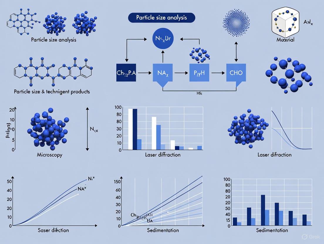
This article provides a comprehensive comparative analysis of particle size analysis techniques essential for researchers and professionals in drug development.
A Comparative Guide to Particle Size Analysis Techniques for Solid-State Products in Pharmaceutical Development
Abstract
This article provides a comprehensive comparative analysis of particle size analysis techniques essential for researchers and professionals in drug development. It explores the foundational principles of prevalent methods, including laser diffraction, dynamic light scattering, dynamic image analysis, and sieving, detailing their specific applications for solid-state products. The content addresses common troubleshooting scenarios and optimization strategies for challenging samples, such as non-spherical crystals and agglomerates. By synthesizing validation data and comparative performance metrics across different techniques, this guide aims to inform robust analytical method selection to enhance product quality, process control, and regulatory compliance in pharmaceutical development.
Understanding Particle Size Analysis: Core Principles and Critical Parameters for Solid-State Products
In pharmaceutical development, the particle size and shape of an Active Pharmaceutical Ingredient (API) are not merely physical attributes but are critical quality attributes that directly influence a drug's safety, efficacy, and manufacturability. The foundational principles governing this relationship are rooted in classical physical chemistry. The Noyes-Whitney equation describes the dissolution rate as being directly proportional to the available surface area of the solid particle, implying that reduced particle size can enhance dissolution [1] [2]. Furthermore, the Ostwald-Freundlich equation establishes that saturation solubility itself can increase for particles in the nanometer range, providing an additional thermodynamic driver for absorption beyond just kinetics [1]. For suspensions, Stokes' law relates particle size to settling velocity, a key factor in ensuring dose uniformity and physical stability of the product [2]. Together, these principles provide a scientific basis for the meticulous control of particle characteristics across all stages of drug product development, from initial formulation to final manufacturing. The goal is to optimize bioavailability—the degree and rate at which a drug is absorbed into the systemic circulation—while ensuring the product can be consistently and reliably manufactured [3] [4].
The Impact of Particle Size on Drug Performance
Solubility and Dissolution Enhancement
Particle size reduction is a primary strategy for improving the performance of poorly soluble drugs (BCS Class II/IV). Reducing particle size increases the specific surface area (surface area per unit mass), which directly enhances the dissolution rate as described by the Noyes-Whitney equation [5]. This relationship is powerfully illustrated by dissolution studies. For example, research on esomeprazole demonstrated that a formulation with a median particle size (X50) of 494 µm had a median dissolution time (T50) of approximately 38 minutes, whereas a larger particle size of 648 µm resulted in a significantly longer T50 of about 61 minutes [5]. This inverse relationship between particle size and dissolution rate is a cornerstone of formulation science.
The following table summarizes key experimental findings from the literature demonstrating the impact of particle size on dissolution and solubility:
Table 1: Experimental Evidence of Particle Size Impact on Dissolution and Solubility
| Drug Substance | Particle Size | Experimental Findings | Source |
|---|---|---|---|
| Coenzyme Q10 Nanocrystals | 80 - 700 nm | Increased kinetic solubility in various dissolution media; dissolution velocity increased as particle size decreased. | [1] |
| Esomeprazole | 494 µm vs 648 µm | Smaller particles (494 µm) reduced median dissolution time (T50) to ~38 min vs ~61 min for larger particles. | [5] |
| General API (from review) | Nanoscale | Smaller particles provide larger specific surface area, promoting dissolution and interaction with cell membranes. | [5] |
Bioavailability and Absorption
The ultimate goal of enhancing dissolution is to improve oral bioavailability. The absorption of a drug involves not just dissolving in the gastrointestinal fluid, but also traversing the intestinal mucosa. Smaller particles, particularly nanoparticles, can leverage different absorption pathways. They can extend residence time in the mucus layer (with pore sizes of 10-200 nm) and enhance penetration through the intestinal wall via persorption, transcellular uptake, and paracellular uptake [5].
Multiple in vivo studies confirm this principle. In beagle dogs, a 0.12 µm formulation of aprepitant achieved a Cmax four times higher than a 5.5 µm formulation [5]. Similarly, rosuvastatin calcium nanoparticles in rabbits showed twice the Cmax and a 1.5-fold increase in AUC (Area Under the Curve, a measure of total exposure) compared to untreated drug [5]. A study on candesartan cilexetil in rats found that 127 nm nanoparticles increased AUC by 2.5-fold and Cmax by 1.7-fold compared to micronized suspensions, also reducing the time to peak concentration (Tmax) [5]. For coenzyme Q10, reducing particle size to 700 nm increased bioavailability (AUC) by 4.4-fold compared to coarse suspensions, with an 80 nm formulation boosting it by 7.3-fold [1].
Table 2: Experimental Evidence of Particle Size Impact on Bioavailability
| Drug Substance | Animal Model | Particle Size & Performance Results | Source |
|---|---|---|---|
| Aprepitant | Beagle Dogs | 0.12 µm formulation achieved a 4x higher Cmax than a 5.5 µm formulation. | [5] |
| Rosuvastatin Calcium | Rabbits | Nanoparticles showed 2x Cmax and 1.5x AUC vs. untreated drug. | [5] |
| Candesartan Cilexetil | Rats | 127 nm nanoparticles increased AUC by 2.5x and Cmax by 1.7x vs micronized suspensions. | [5] |
| Coenzyme Q10 | Beagle Dogs | 700 nm particles: 4.4x AUC vs coarse; 80 nm particles: 7.3x AUC vs coarse. | [1] |
Performance in Long-Acting Injectables (LAIs)
Particle size plays a uniquely critical role in the performance of long-acting injectable (LAI) crystalline aqueous suspensions. For these formulations, which are used to treat chronic diseases like HIV and neurological disorders, the drug absorption is often dissolution-rate limited [6] [7]. A larger particle size dissolves more slowly, providing sustained release over weeks or months. However, this requires a careful balance. While larger particles prolong release, they also increase sedimentation rates, raise the risk of needle clogging, and can cause injection pain due to higher back pressure [6]. Consequently, identifying the optimal particle size distribution (PSD) is a multidimensional challenge that balances pharmacokinetics with injectability, stability, and patient tolerance [6] [7].
Processability and Manufacturing
The influence of particle size extends beyond bioperformance into the practical realm of manufacturing and processability. Powder flowability is crucial for efficient tableting, and smaller particles generally flow less efficiently than larger, more uniform ones [4]. Poor flow can lead to variations in tablet weight and content uniformity. Furthermore, particle compressibility is affected by size; very fine particles may lack the ability to lock together effectively during compression, leading to defects such as capping (horizontal separation of the top or bottom of a tablet) or lamination (layer separation within the tablet) [4]. The presence of excessive fines (small, dusty particles) also reduces overall yield, increases cleaning costs, and accelerates machine wear [4]. Therefore, controlling particle size distribution is essential for robust, cost-effective, and high-quality pharmaceutical manufacturing.
The Critical Role of Particle Shape
While particle size is often the primary focus, particle shape is an equally critical parameter that can profoundly influence product performance and processing. Laser diffraction, a common sizing technique, assumes spherical particles, but real-world API crystals are rarely perfect spheres [2]. The shape of a particle directly affects its surface roughness, which in turn influences the actual surface area available for dissolution—a fact that can explain why smaller particles do not always dissolve faster than larger ones with a rougher surface morphology [2].
Shape also dictates powder flow and compaction behavior. In direct compression tableting, particle shape influences segregation behavior and compressibility, which affects the consistency of tablet weight, composition, and the mechanical properties of the final tablet [2]. For suspensions, particle shape, in conjunction with size distribution and zeta potential, impacts the stability of the dispersion and the rate of settling or aggregation [2]. Modern automated imaging techniques allow for the quantitative analysis of shape descriptors such as circularity, convexity, and elongation, providing a more complete material characterization than size analysis alone [2].
Analytical Techniques for Particle Characterization
A variety of analytical techniques are available for particle size and shape analysis, each with its own principles, advantages, and limitations. The choice of method depends on the sample's properties, the required size range, and the information needed (size vs. size and shape).
Table 3: Comparison of Particle Size and Shape Analysis Techniques
| Technique | Measured Parameter | Typical Size Range | Key Advantages | Key Limitations |
|---|---|---|---|---|
| Laser Diffraction (LD) [8] [9] | Equivalent Spherical Diameter (Volume-based) | 0.01 µm - 2 mm | Wide size range, fast, high repeatability, suitable for dry powders and dispersions. | Assumes spherical particles; sampling errors can affect results. |
| Dynamic Light Scattering (DLS) [8] [9] | Hydrodynamic Diameter | 0.3 nm - 10 µm | Fast, good for proteins and nanoparticles in suspension. | Assumes spherical particles; struggles with polydisperse samples; sensitive to temperature. |
| Dynamic Image Analysis (DIA) [8] [9] | Size and Shape (e.g., aspect ratio, circularity) | 2 µm - 3 mm | Provides direct shape and size data for individual particles. | Not suitable for nanoparticles; sample preparation can be complex. |
| Sieving [8] [9] | Particle Size (Mass-based) | 30 µm - 120 mm | Low cost, robust, widely accepted. | Time-consuming; assumes spherical particles for size classification. |
| Scanning Electron Microscopy (SEM) [8] | Size, Shape, Surface Morphology | > 10 nm | High-resolution images, detailed surface and shape information. | Sample must be dry and often coated; analysis is slow and not statistical. |
| Nanoparticle Tracking Analysis (NTA) [9] | Hydrodynamic Diameter (Number-based) | 30 nm - 1 µm | Measures concentration; good for polydisperse samples. | Less reproducible than DLS; time-consuming; requires experienced users. |
The following workflow diagram illustrates the decision-making process for selecting an appropriate characterization technique based on the primary analytical need:
It is crucial to note that different techniques can yield different results for the same sample, as they are based on different measurement principles (e.g., volume-based vs. number-based distributions) and make different assumptions about particle shape [2] [9]. Therefore, comparing results from different methods should be done with caution, and it is often beneficial to use techniques like imaging to complement and validate data from laser diffraction or DLS [2].
Experimental Protocols for Particle Size Studies
Protocol 1: Nanoparticle Formation via Liquid Antisolvent Crystallization with Focused Ultrasonication
This protocol is used to produce nanoscale drug particles, such as a Cinnarizine formulation with a target particle size below 200 nm [5].
- Preparation: Dissolve the API in a suitable organic solvent (e.g., ethanol) to form the organic phase. Heat may be applied (e.g., 60°C water bath) to facilitate dissolution.
- Precipitation: Rapidly inject the organic phase into a nonsolvent (e.g., distilled water) under controlled conditions. Key parameters include:
- Injection rate: Varies (e.g., 30 mL/min for 400 nm particles, 15 mL/min for 700 nm particles).
- Stirring speed: Varies (e.g., 800 rpm for 400 nm particles, 400 rpm for 700 nm particles).
- Size Reduction: Subject the resulting suspension to focused ultrasonication using a device like a Covaris instrument with Adaptive Focused Acoustics (AFA) technology.
- Duration: ~4500 seconds.
- Bath Temperature: 10°C.
- Power Mode: Frequency sweeping.
- Degassing Mode: Continuous.
- Concentration (Optional): Concentrate the final nanosuspension using methods like ultrafiltration if needed.
Protocol 2: In Vivo Bioavailability Study in Beagle Dogs
This protocol assesses the impact of particle size on oral absorption [1].
- Formulation Preparation: Prepare suspensions of the drug with different, well-characterized particle sizes (e.g., coarse suspension vs. 80 nm, 120 nm, 400 nm, and 700 nm nanocrystals). Adjust drug content to the desired concentration (e.g., ~1 mg/mL).
- Animal Dosing: Use beagle dogs as the model organism. Administer the formulations orally in a cross-over study design.
- Blood Sampling: Collect blood samples at predetermined time points post-administration over a specified period (e.g., 0-48 hours).
- Bioanalysis: Process plasma samples and quantify drug concentration using a validated analytical method, typically reverse-phase High-Performance Liquid Chromatography (HPLC).
- Pharmacokinetic Analysis: Calculate key pharmacokinetic parameters from the plasma concentration-time profile, including:
- AUC0-48: Area under the curve, indicating total drug exposure.
- Cmax: Maximum plasma concentration.
- Tmax: Time to reach Cmax.
The Scientist's Toolkit: Essential Reagents and Materials
Table 4: Key Research Reagents and Materials for Particle Size Studies
| Item | Function/Application | Examples & Notes |
|---|---|---|
| Solvents & Antisolvents | Used in liquid antisolvent crystallization to precipitate nanoparticles. | Ethanol, isopropanol, water. Must not dissolve the final particles [1] [5]. |
| Stabilizers & Surfactants | Prevent aggregation and Ostwald ripening in nanosuspensions. | Tween 20, various polymers. Critical for long-term stability [1]. |
| Dispersion Media | Medium for particle size analysis of dispersions (LD, DLS). | Aqueous or organic solvents that do not interact with or dissolve the particles [8]. |
| HPLC-grade Solvents | For bioanalysis of in vivo samples to determine drug concentration in plasma. | Methanol, ethanol; used in reverse-phase HPLC [1]. |
| Standard Sieves | For traditional sieve analysis to determine particle size distribution by mass. | Assembled into a stack with decreasing mesh size according to ASTM/ISO standards [8] [9]. |
| Focused Ultrasonicator | Equipment for precise nanoparticle size reduction. | Covaris instrument with Adaptive Focused Acoustics (AFA) [5]. |
| Laser Diffraction Analyzer | Instrument for rapid, volume-based particle size distribution analysis. | Malvern analyzers; complies with ISO 13320 and USP <429> [8] [2]. |
The following diagram summarizes the logical relationships and workflows involved in a particle size reduction and characterization study as discussed in the protocols:
Particle size and shape are foundational material characteristics that exert a profound influence on the critical quality attributes of a pharmaceutical product. A deep understanding of their impact on solubility, dissolution, bioavailability, and processability is non-negotiable for successful drug development. Selecting the appropriate analytical technique is paramount, as different methods provide complementary information and can sometimes yield conflicting results. The chosen strategy for particle engineering—whether through micronization, nanonization, or controlled crystallization—must be a carefully balanced decision that aligns with the Target Product Profile (TPP). This decision must holistically consider the desired pharmacokinetics, stability, manufacturability, and patient experience. As pharmaceutical science continues to tackle increasingly complex and poorly soluble drug molecules, the precise control and thorough characterization of particle properties will remain a cornerstone of developing safe, effective, and high-quality medicines.
In the field of solid-state products research, particularly in pharmaceutical development, the precise characterization of materials is fundamental to ensuring product quality, performance, and stability. Particle properties such as size, shape, and the permeability of porous matrices directly influence critical parameters including dissolution rates, bioavailability, compressibility, and flow characteristics [10] [11] [12]. This guide provides an objective comparison of three pivotal analytical technique categories: light scattering, image analysis, and permeability measurement. By outlining the core principles, applicable standards, experimental protocols, and relative strengths and limitations of each method, this document serves to inform researchers and scientists in selecting the most appropriate characterization strategy for their specific application needs.
Core Principles and Techniques
Light Scattering
Light scattering techniques operate on the principle of measuring the interaction between a beam of light and dispersed particles to extract information about their size and distribution [12].
Static Light Scattering (SLS) / Laser Diffraction (LD): This method analyzes the time-averaged angular dependence of scattered light intensity. When a laser illuminates a sample, larger particles scatter light at smaller angles with higher intensity, while smaller particles scatter light at wider angles with lower intensity [13] [12]. The resulting scattering pattern is analyzed using algorithms based on Mie theory or the Fraunhofer approximation to calculate a volume-based particle size distribution [11] [13]. Laser diffraction is a rapid, high-throughput method covering a broad size range from sub-micron to several millimeters, making it a versatile tool for quality control [8] [11] [12].
Dynamic Light Scattering (DLS): Used primarily for nano-scale particles, DLS analyzes the time-dependent fluctuation in scattering intensity caused by the Brownian motion of particles in a dispersion [12]. Smaller particles diffuse more rapidly, causing faster intensity fluctuations, while larger particles move more slowly and cause slower fluctuations [8] [14]. An autocorrelation analysis of these fluctuations yields the diffusion coefficient, from which a hydrodynamic diameter is calculated via the Stokes-Einstein equation [14] [15]. DLS is ideal for proteins, nanoparticles, and microemulsions in the size range of 0.3 nm to 10 μm [8] [14].
Figure 1: Core light scattering measurement workflow.
Image Analysis
Image analysis provides a direct method for determining particle size and shape by capturing and analyzing digital images of individual particles [10] [16]. This technique does not assume spherical geometry, making it uniquely powerful for characterizing irregularly shaped particles such as rods or fibers [16].
The process involves four key steps [16]:
- Image Taking: A digital camera, often coupled with a microscope, captures images of dispersed particles, either stationary on a substrate or in motion.
- Image Processing: Software enhances image quality by eliminating noise, correcting brightness variations, and separating connected particles.
- Object Detection: Through "thresholding," each pixel is assigned to either a particle or the background, allowing the software to identify individual particles.
- Classification: Detected particles are classified based on extracted size and shape parameters (e.g., equivalent circular area diameter, length, width, aspect ratio) and grouped into distribution classes [10] [16].
Image analysis can be performed in static or dynamic mode. Static Image Analysis (SIA) examines particles on a static substrate, while Dynamic Image Analysis (DIA) captures images of particles flowing past a camera, enabling the analysis of a larger, more statistically significant number of particles in a random orientation [11] [14].
Figure 2: Image analysis workflow for particle characterization.
Permeability
Permeability measurement quantifies the ability of a fluid to flow through a porous medium, such as a packed powder bed or a reservoir rock core sample [17]. The standard methodology is based on Darcy's Law, which for a linear, incompressible flow is expressed as [17]:
[ Q = \frac{K A \Delta P}{\mu L} ]
Where:
- ( Q ) = volumetric flow rate
- ( K ) = permeability of the medium
- ( A ) = cross-sectional area to flow
- ( \Delta P ) = pressure drop across the medium
- ( \mu ) = dynamic viscosity of the fluid
- ( L ) = length of the medium
Two common experimental methods for measuring liquid permeability are [18]:
- Constant Head Method (CHM): Maintains a constant pressure differential across the sample during measurement. This method is fast, has low standard deviation, and is recommended for standardization, particularly for samples with pore sizes below 30 µm that require laminar flow conditions [18].
- Falling Head Method (FHM): Uses a declining pressure differential and is recommended for highly permeable samples where turbulent flow is present [18].
A critical consideration is the Klinkenberg Effect, which occurs when gases are used as the testing fluid. Due to gas molecule slippage along pore walls at low pressures, the measured gas permeability is higher than the intrinsic (liquid) permeability. This effect is significant for low-permeability materials and fine powders, and requires data extrapolation from multiple pressure measurements to determine the true absolute permeability [17].
Comparative Analysis of Techniques
Technical Comparison Table
Table 1: Comparative overview of key particle characterization techniques.
| Parameter | Laser Diffraction (LD) | Dynamic Light Scattering (DLS) | Image Analysis (DIA/SIA) | Permeability Measurement |
|---|---|---|---|---|
| Measured Property | Particle size distribution (Volume-based) [11] | Hydrodynamic diameter (Size distribution) [8] [14] | Particle size & shape distributions (Number-based) [10] [11] | Permeability of a porous medium [17] |
| Principle | Angle & intensity of scattered light [13] | Brownian motion & fluctuation of scattered light [12] | Direct imaging & digital analysis [16] | Fluid flow through a porous sample (Darcy's Law) [17] |
| Typical Size Range | 0.01 µm – 2000 µm [8] | 0.3 nm – 10 µm [8] | 0.5 µm – 3000 µm [8] [10] | N/A (Property of a packed bed or solid) |
| Sample Matrix | Dry powders or liquid dispersions [8] | Liquid dispersions only [8] | Dry powders, liquid suspensions, filters [10] | Core samples (e.g., compressed powder) [17] |
| Shape Sensitivity | Assumes spherical particles [8] | Assumes spherical particles [8] | Measures shape directly (e.g., aspect ratio, circularity) [10] [16] | Indirectly inferred from flow resistance |
| Throughput | High (Rapid analysis) [11] | Medium to High [12] | Low to Medium (Longer analysis times) [10] [11] | Medium (Requires sample preparation) [17] |
| Key Advantage | Wide size range, speed, high throughput [11] | Small particle sensitivity, measures in native solution [8] [12] | Direct visualization, no shape assumption, detects outliers [10] [14] | Directly measures a critical performance property [17] |
| Key Limitation | Inaccurate for non-spherical particles [8] [11] | Limited to nanoscale/submicron particles [14] | Low throughput, not for nanoparticles [10] [11] | Klinkenberg effect (if using gas) [17] |
Performance Data and Experimental Comparisons
Independent studies and technical reviews provide critical data for comparing the performance of these techniques in practical scenarios.
Table 2: Experimental findings and performance characteristics.
| Technique Comparison | Experimental Context | Key Findings & Performance Data |
|---|---|---|
| Laser Diffraction vs. Image Analysis | Analysis of ground coffee and cellulose fibers [14] | • LD results correspond to the area-equivalent diameter from DIA, but distributions appear broader as all particle dimensions are included and related to spheres [14].• For fibers, DIA differentiates between fiber width (~20 µm) and length (~400 µm), while LD produces a single, broad distribution that runs parallel to the width measurement before approaching the fiber length, failing to resolve the two dimensions [14]. |
| Permeability Methods (CHM vs. FHM) | Water permeability of woven filter meshes [18] | • Constant Head Method (CHM): Recommended for standardization. It was the fastest method with the lowest standard deviation and could provide laminar flow conditions for samples with pore sizes below 30 µm [18].• Falling Head Method (FHM): Operated only under turbulent flow and was thus recommended only for highly permeable samples [18].• All techniques (CHM, FHM, simulation) showed good agreement when working under a turbulent regime (pore size > 30 µm) [18]. |
| Detection Sensitivity | General capability of various techniques [14] | • Dynamic Image Analysis (DIA): Excellent sensitivity for oversized particles, with a detection limit as low as 0.01% [14].• Laser Diffraction (SLS): Relatively low sensitivity; modern analyzers can detect oversized grains only from approximately 2% by volume [14]. |
Detailed Experimental Protocols
Laser Diffraction (LD) Protocol
- Sample Preparation: For dry powders, use a vibrating feeder or air dispersion to ensure a steady, agglomerate-free stream of particles through the measurement zone. For liquid dispersions, select a suitable solvent that does not dissolve or react with the particles, and use sonication or stirring to achieve a homogeneous dispersion [8].
- Instrument Setup: Input the optical properties of the material, specifically the real and imaginary parts of the refractive index, for accurate application of Mie theory, which is crucial for particles below 20 µm [13].
- Measurement: Pass the dispersed sample through the laser beam. The optical system, comprising multiple light sources and a wide array of detectors, captures the scattered light pattern over a broad angular range [13] [12].
- Data Analysis: The instrument software inverts the scattered light data using Mie theory or the Fraunhofer approximation to compute a volume-based particle size distribution. Key percentiles such as D10, D50, and D90 are reported [11] [13].
Dynamic Image Analysis (DIA) Protocol
- Sample Dispersion: Disperse the sample in a suitable dry or wet state. For dry powders, a vibrating feeder or compressed air can be used to separate and convey particles. For liquids, disperse the powder in a solvent and pump the suspension through a flow cell [10] [16].
- Image Acquisition: As particles pass in a continuous flow through the detection zone, a pulsed light source (e.g., LED) and a high-speed camera capture high-resolution images of each particle [14].
- Image Processing and Analysis: The software performs thresholding to distinguish particles from the background. It then analyzes each particle image to determine a suite of size (e.g., length, width, equivalent circular area diameter) and shape (e.g., aspect ratio, circularity, convexity) parameters [10] [14].
- Data Reporting: Results are compiled into number-based distributions for size and shape. The system can analyze hundreds of thousands of particles to ensure statistical significance, and images are available for visual verification [10] [11].
Gas Permeability Protocol (with Klinkenberg Correction)
- Sample Preparation: For powdered materials, compress into a solid compact or core plug of known dimensions (length and diameter). The sample must be dried to remove any residual fluids [17].
- Core Holder Setup: Place the core sample in a holder and apply a confining pressure to simulate overburden stress and prevent fluid bypass [17].
- Flow Experiment: Flow a gas (e.g., air, nitrogen) through the sample at multiple, controlled flow rates. Precisely measure the flow rate (Q) and the upstream and downstream pressures (P1, P2) for each flow rate [17].
- Data Processing & Klinkenberg Correction:
- Calculate the apparent gas permeability (K_g) for each data point using Darcy's law.
- Plot the apparent gas permeability (Kg) against the inverse of the mean pressure (1/Pm).
- Fit a straight line through the data points. The intercept of this line at infinite pressure (where 1/Pm = 0) yields the absolute liquid permeability (KL) [17].
The Scientist's Toolkit: Essential Research Reagents and Materials
Table 3: Key reagents, materials, and equipment for particle characterization experiments.
| Item Name | Function/Application | Technical Notes |
|---|---|---|
| Dispersion Solvents | Liquid medium for dispersing powder samples in LD, DLS, and DIA [8]. | Must not dissolve or interact with the particles. Common choices include water, isopropanol, and cyclohexane. Salinity can be adjusted to prevent clay swelling in certain samples [8] [17]. |
| Standard Sieves | For pre-fractionating or comparative sieve analysis of coarse powders [8]. | Used according to ASTM or ISO standards. A stack with gradually decreasing apertures (30 µm to 120 mm) is assembled for gravimetric analysis [8]. |
| Refractive Index (RI) Standards | Verification of instrument alignment and accuracy in light scattering [13]. | Materials with known and stable RI are used to validate the performance of laser diffraction analyzers. |
| CZR Resin (Cyclohexanol) | A common solvent for preparing sample suspensions, particularly where water reactivity is a concern. | Ensves particles do not dissolve or undergo morphological changes during analysis in LD or DIA [8]. |
| Core Holder & Permeameter | Assembly for housing and testing the permeability of core samples or powder compacts [17]. | Applies confining pressure and allows for precise application of fluid pressure gradients and measurement of flow rates. |
| Metal or Carbon Coating | Preparation of non-conductive samples for Scanning Electron Microscopy (SEM) [8]. | A thin, conductive layer is applied to prevent charging and improve image quality for detailed shape and surface morphology analysis. |
| Soxhlet Extractor | Laboratory setup for thorough cleaning and drying of core samples before permeability testing [17]. | Removes residual fluids (e.g., water, oil) to ensure the core is 100% saturated with air before measurement. |
The selection of an appropriate characterization technique is paramount in solid-state research and drug development. Laser Diffraction stands out for its speed and wide size range, making it ideal for quality control where high throughput is essential, though its assumption of sphericity is a key limitation. Dynamic Light Scattering is the technique of choice for sub-micron and nano-scale particles in suspension, providing critical size information for proteins and nanomedicines. Image Analysis is unparalleled when particle shape is a critical performance attribute, offering direct visualization and quantification of morphology without shape assumptions, despite its lower throughput. Finally, Permeability Measurement provides unique insights into the bulk fluid transport properties of porous matrices, which is vital for understanding dissolution and filtration.
No single technique provides a complete picture for all materials and applications. The synergistic use of these methods—for instance, using LD for routine quality control and DIA for investigating process-induced shape changes—often yields the most comprehensive understanding of particle properties, ultimately guiding the development of more effective and reliable solid-state products.
Particle size analysis is a fundamental aspect of solid-state research, influencing everything from drug bioavailability to the mechanical properties of materials. However, most analytical techniques do not measure size directly but instead report an Equivalent Spherical Diameter (ESD), the diameter of a sphere that would behave identically to the particle under a specific measurement condition [19] [20]. This guide provides a comparative analysis of major particle sizing techniques, detailing their operating principles, reported ESDs, and the critical role of shape descriptors to equip researchers with the knowledge to accurately interpret data and select the optimal methodology.
Fundamentals of Equivalent Spherical Diameter
The ESD is a foundational concept in particle size analysis because it provides a standardized way to describe non-spherical, irregular particles using a single, comparable parameter [19]. The specific ESD reported varies drastically with the measurement principle, meaning that a single particle can have different "sizes" depending on the technique used [20]. The table below summarizes the most common types of ESDs.
Table 1: Common Types of Equivalent Spherical Diameters (ESD)
| Equivalent Spherical Diameter (ESD) Type | Definition | Primary Measurement Technique(s) |
|---|---|---|
| Volume-equivalent Diameter | The diameter of a sphere having the same volume as the particle [19] [20]. | Laser Diffraction [19] [20]. |
| Area-equivalent Diameter | The diameter of a sphere having the same projected area as the particle [19] [20]. | Static and Dynamic Image Analysis [19] [20]. |
| Sieve-equivalent Diameter | The diameter of a sphere that passes through the same sieve aperture as the particle [19] [20]. | Sieve Analysis [19] [20]. |
| Stokes Diameter | The diameter of a sphere having the same density and settling velocity as the particle [19] [20]. | Sedimentation Analysis [19] [20]. |
| Hydrodynamic Diameter | The diameter of a sphere that diffuses at the same rate as the particle in a specific fluid [9] [20]. | Dynamic Light Scattering (DLS), Nanoparticle Tracking Analysis (NTA) [9] [20]. |
Comparative Analysis of Particle Sizing Techniques
Different particle sizing techniques are suited for different size ranges, sample types, and provide distinct ESDs. The following table offers a direct comparison of the most prevalent methods.
Table 2: Comparison of Common Particle Size Analysis Techniques
| Method | Measurement Principle | Measured ESD | Typical Size Range | Key Advantages | Key Limitations |
|---|---|---|---|---|---|
| Laser Diffraction (LD) | Analyzes the scattering pattern of laser light by particles [9] [21]. | Volume-equivalent diameter [19] [20]. | ~0.01 µm to 2000 µm [9] [8]. | High throughput, broad size range, suitable for wet or dry dispersion [9] [21]. | Assumes spherical particles; results are approximations for non-spherical ones [9] [8]. |
| Dynamic Light Scattering (DLS) | Measures Brownian motion to determine diffusion coefficient [9] [21]. | Hydrodynamic diameter [9] [20]. | ~0.3 nm to 10 µm [9] [8]. | Fast, calibration-free, ideal for proteins and nanoparticles in suspension [9]. | Low resolution for polydisperse samples; sensitive to aggregates and temperature [9] [21]. |
| Dynamic Image Analysis (DIA) | Captures and analyzes images of individual particles in flow [9]. | Area-equivalent diameter, Feret diameters [9] [20]. | ~2 µm to 3000 µm [8]. | Provides direct shape and morphological data (e.g., aspect ratio, circularity) [9]. | Not suitable for nanoparticles; lower throughput than LD or DLS [9] [8]. |
| Sieving | Separates particles by size via mechanical vibration through mesh screens [9] [22]. | Sieve-equivalent diameter [19] [20]. | ~20 µm to 120 mm [9] [8]. | Simple, robust, low-cost, and widely accepted [9]. | Time-consuming; low resolution for fine particles; results sensitive to particle orientation [9] [22]. |
| Sedimentation | Determines size from settling velocity under gravity or centrifugal force using Stokes' law [9] [22]. | Stokes diameter [19] [20]. | ~1 µm to 100 µm [9]. | High accuracy and repeatability for spherical particles in its range [9]. | Slow for small particles; biased by density differences and Brownian motion [9]. |
| Nanoparticle Tracking Analysis (NTA) | Tracks and analyzes the Brownian motion of individual particles via light scattering [9] [23]. | Hydrodynamic diameter [9] [20]. | ~30 nm to 1000 nm [9]. | Provides number-based distribution and concentration data for polydisperse nano-suspensions [9] [23]. | Less reproducible and more time-consuming than DLS; requires experienced users [9]. |
Experimental Protocols and Methodologies
Laser Diffraction (ISO 13320)
Laser diffraction is a high-throughput technique favored in quality control for its speed and broad dynamic range [9] [21].
Detailed Protocol:
- Sample Dispersion: The solid sample must be fully dispersed in a suitable medium (e.g., water, organic solvents) that does not dissolve or react with the particles. Surfactants may be added to break agglomerates [19]. Dry powder dispersion via air pressure is also common [19].
- Background Measurement: A measurement of the pure dispersion medium is first taken to establish a baseline "background" signal [19].
- Sample Measurement: The dispersed sample is passed through the laser beam, and detectors measure the intensity of light scattered at various angles [9] [21].
- Data Analysis: The instrument's software uses Mie theory or the Fraunhofer approximation to calculate a volume-based particle size distribution from the scattering pattern. The refractive indices of both the particle and the dispersion medium are critical inputs for this calculation [19] [9]. The results are expressed as a volume-weighted distribution, and key parameters like Dv10, Dv50, Dv90, and the De Brouckere mean diameter D[4,3] are reported [9].
Dynamic Image Analysis (ISO 13322-2)
DIA is used when particle shape is a critical attribute, such as in catalyst or granule analysis [9].
Detailed Protocol:
- Sample Presentation: Particles are dispersed in a liquid or air and passed as a thin stream in front of a high-speed camera and a pulsed light source to "freeze" motion [9].
- Image Acquisition & Thresholding: The system captures thousands of images. Software distinguishes particles from the background based on contrast (thresholding) [9].
- Particle Measurement: For each detected particle, multiple size and shape parameters are measured [9] [20]:
- Area-equivalent diameter: Calculated from the pixel count of the particle's projection.
- Feret Diameters: The distance between parallel tangents at different angles (e.g., Max Feret, Min Feret).
- Shape Descriptors: Parameters like Aspect Ratio (Min Feret / Max Feret), Circularity, and Roundness are calculated.
- Data Reporting: Results are typically number-based distributions. The analysis provides a comprehensive dataset linking individual particle size to its specific shape morphology [9].
Visual Workflow for Technique Selection
The following diagram illustrates the logical decision process for selecting an appropriate particle sizing technique based on key sample and research criteria.
The Scientist's Toolkit: Essential Research Reagents and Materials
Successful particle size analysis requires not only the right instrument but also the appropriate consumables and reagents to ensure a representative and stable measurement.
Table 3: Essential Materials for Particle Size Analysis
| Item | Function | Key Considerations |
|---|---|---|
| Dispersion Media | Liquid in which solid particles are suspended for wet measurement [19] [8]. | Must not dissolve or chemically react with the sample. Common choices are water, isopropanol, or cyclohexane [8]. |
| Surfactants | Chemicals added to a dispersion medium to break apart agglomerates and improve particle separation [19]. | Critical for measuring fine powders. Type (ionic/non-ionic) and concentration must be optimized to avoid altering the native particle state [19]. |
| Standard Sieve Stack | A set of sieves with precisely calibrated mesh sizes for sieve analysis [9] [8]. | Sieves must conform to ASTM or ISO standards. The stack is assembled with the largest mesh at the top and the smallest at the bottom [9] [8]. |
| Refractive Index (RI) | An optical property of both the particle and dispersion medium [19]. | Accurate RI values for the sample and medium are mandatory for correct analysis in laser diffraction using Mie theory [19] [9]. |
| Certified Reference Materials | Particles with a known, certified size distribution [24]. | Used for method development and regular instrument qualification/calibration to ensure data accuracy and compliance [24]. |
Selecting the right particle size analysis technique requires a clear understanding that different methods report different Equivalent Spherical Diameters. Laser diffraction offers high-throughput, volume-based data ideal for quality control, while image analysis provides invaluable shape descriptors for understanding particle behavior. Techniques like DLS and NTA are essential for the nano-regime. The choice is not about finding the one "true" size, but about applying the correct tool to obtain the most relevant ESD for your specific application, whether it is optimizing drug bioavailability, ensuring powder flowability, or controlling product stability.
Selecting the optimal particle size analysis technique is a critical step in solid-state research, as the choice directly influences the accuracy and relevance of the data obtained. No single method is universally superior; instead, the optimal selection is dictated by a interplay of three core parameters: the expected particle size range, the particle shape, and the nature of the sample matrix. This guide provides a comparative analysis of common techniques to inform researchers and development professionals in making data-driven method selection decisions.
Comparative Analysis of Particle Sizing Techniques
The table below summarizes the fundamental characteristics of common particle size analysis techniques, providing a high-level overview for initial method screening.
Table 1: Key Characteristics of Common Particle Sizing Techniques
| Method | Suitable Particle Shapes | Typical Size Range | Sample Matrix | Method Principle |
|---|---|---|---|---|
| Laser Diffraction (LD) [8] | Spherical [8] | 0.01 µm - 2,600 µm (up to 3,500 µm with imaging) [25] [8] | Dry powders or liquid dispersions [8] | Scattering/diffraction pattern of laser light [9] [8] |
| Dynamic Light Scattering (DLS) [8] | Spherical [8] | 0.3 nm - 10 μm [8] | Liquid dispersions [8] | Brownian motion (Hydrodynamic diameter) [9] [8] |
| Dynamic Image Analysis (DIA) [9] | All shapes [8] | 30 μm - 10,000 μm [9] [26] | Dry powders [9] [26] | Optical imaging of flowing particles [9] |
| Static Image Analysis | All shapes | 0.3 μm - 10,000 μm [26] | Dry & Wet dispersions [26] | Optical imaging of static particles [26] |
| Scanning Electron Microscopy (SEM) [8] | All shapes [8] | > 10 nm [8] | Dry powders (requires conductive coating) [8] | High-resolution electron imaging [21] [8] |
| Sieve Analysis [8] | All shapes [8] | 30 µm - 120 mm [8] | Dry powders [8] | Gravimetric separation by mesh size [9] [8] |
| X-ray Computed Tomography (XCT) [24] | All shapes (3D data) | Not specified (3D volumetric technique) | Solid volume | 3D X-ray imaging [24] |
Detailed Methodologies and Experimental Protocols
Laser Diffraction (LD)
- Principle: A laser beam passes through a dispersed sample, and particles scatter light at angles inversely proportional to their size. Detectors measure the intensity pattern, and complex algorithms based on Mie theory compare these measurements to theoretical values to calculate a volume-based particle size distribution (PSD) [9] [21].
- Experimental Protocol: The sample is dispersed in a suitable dry or liquid medium to ensure a representative concentration that avoids multiple scattering. The obscuration level is checked to fall within the instrument's recommended range. The measurement is rapid, taking seconds to minutes, and results are typically presented as D-values (D10, D50, D90) and a distribution graph [9] [21].
Dynamic Light Scattering (DLS)
- Principle: Also known as Photon Correlation Spectroscopy, DLS measures the random Brownian motion of particles suspended in a liquid. Smaller particles move faster than larger ones. A laser beam hits the particles, and the fluctuations in scattered light intensity are detected. These fluctuations are analyzed via an autocorrelation function, and the translational diffusion coefficient is used in the Stokes-Einstein equation to calculate the hydrodynamic diameter [9].
- Experimental Protocol: A dilute, dust-free suspension is essential. The sample is loaded into a cuvette, and the temperature is precisely controlled, as viscosity is a key parameter. Measurement times are typically a few minutes. Results include a hydrodynamic diameter and a polydispersity index (PDI) indicating the breadth of the distribution [9].
Image Analysis (Static and Dynamic)
- Principle: This technique captures two-dimensional projections of individual particles. For each particle, software calculates numerous size and shape parameters [26]. Static image analysis observes particles on a stationary substrate, while dynamic image analysis captures images of particles as they flow past a camera [9] [26].
- Experimental Protocol: The sample must be well-dispersed to prevent particle overlap. For dynamic analysis, a representative sample is fed through a flow cell. The software analyzes thousands of particles to build a number-based distribution. Measurable parameters include Feret diameters (max and min), aspect ratio, circularity, and length/width ratio [26].
X-ray Computed Tomography (XCT)
- Principle: XCT is a non-destructive technique that generates 3D volumetric data of a sample by collecting a series of 2D X-ray images from different angles. These projections are computationally reconstructed into a 3D model, allowing for the analysis of internal and external structures without physical sectioning [24].
- Experimental Protocol: A solid sample is mounted on a stage that rotates within the X-ray beam. The scan parameters (energy, resolution, exposure time) are set based on the material's density and the required resolution. The 3D data set can be segmented to identify individual particles, allowing for the measurement of true 3D size, shape, orientation, and even intraparticle porosity [24].
Experimental Data and Performance Comparison
A comparative study of laboratory-based techniques using spherical silica particles with known size ranges provides critical insights into method-specific biases [24].
Table 2: Experimental Findings from a Geoscience Study on Silica Spheres [24]
| Method | Reported Accuracy for <150 μm | Reported Accuracy for >150 μm | Key Limitation / Cause of Error |
|---|---|---|---|
| Laser Particle Size Analysis (LPSA) | Agrees with other techniques | Overestimates particle size | Calculation limitation of the technique |
| Optical Point Counting | Agrees with other techniques | Underestimates particle size | Stereology (effect of slicing particles) |
| 2D Automated Image Analysis | Agrees with other techniques | Underestimates particle diameter | Stereology (effect of slicing particles) |
| X-ray Computed Tomography (XCT) | Agrees with other techniques | Most accurate; lowest sorting values | 3D volumetric analysis avoids stereological errors |
The study concluded that XCT was the most accurate method for determining grain size distribution in sediments, as it is the only 3D analysis method that avoids the stereological errors inherent in 2D techniques [24].
The Scientist's Toolkit: Essential Research Reagent Solutions
Table 3: Key Materials and Reagents for Particle Size Analysis
| Item | Function / Application |
|---|---|
| Spherical Silica Particles [24] | Reference materials for method calibration and validation of particle sizing techniques. |
| Isotope-labelled Internal Standards [27] [28] | Used in mass spectrometry to correct for matrix effects and ensure accurate quantitation. |
| Electrolyte Solutions [9] | Required for particle size analysis based on the Coulter principle, which relies on electrical conductivity. |
| Aqueous & Non-aqueous Dispersion Media [8] | Liquids (e.g., water, surfactants, organic solvents) used to create stable suspensions for laser diffraction, DLS, and image analysis. |
| Matrix-Matched Standards [29] [27] | Calibration standards with a composition similar to the sample, used to compensate for matrix effects in techniques like XRF and SIMS. |
Decision Framework and Visual Workflow
The following diagram outlines a logical workflow for selecting a particle size analysis method based on the three critical parameters.
Particle size analysis is a foundational characterization in solid-state product research. The comparative data and frameworks presented here underscore that a deliberate, parameter-driven selection process—prioritizing particle size range, shape, and sample matrix—is essential for generating reliable and meaningful data to guide research and development.
A Practical Guide to Particle Sizing Techniques: From Laser Diffraction to Image Analysis
Laser Diffraction (LD) has become one of the most widely used particle sizing techniques across numerous industries, including pharmaceuticals, chemicals, and materials science. As an ensemble technique that measures particle size distributions by analyzing the angular variation of scattered light, LD offers rapid analysis for materials ranging from hundreds of nanometers to several millimeters [30]. The technique's widespread adoption is supported by international standardization, most notably ISO 13320:2020, which provides comprehensive guidance on instrument qualification and size distribution measurement of particles in two-phase systems such as powders, sprays, aerosols, suspensions, and emulsions [31].
For researchers and drug development professionals, understanding the operational principles, regulatory compliance, and practical applicability of LD is crucial for obtaining reliable particle size data. Particle size is a critical quality attribute that profoundly impacts material performance and properties, influencing everything from the dissolution rate of pharmaceutical ingredients to the texture of food products and the efficiency of industrial catalysts [32]. This guide objectively examines LD technology within the context of particle size analysis techniques for solid-state research, comparing its performance with alternative methods and providing supporting experimental data.
Operational Principles of Laser Diffraction
Fundamental Light Scattering Theory
The underlying principle of laser diffraction particle sizing is based on the relationship between particle size and light scattering patterns. When a laser beam passes through a dispersed particulate sample, particles scatter light at angles inversely proportional to their size [33]. Large particles scatter light at small angles relative to the laser beam, while small particles scatter light at wide angles [30]. The angular scattering intensity data is collected by a detector array and analyzed through appropriate optical models to calculate particle size distribution.
The measurement principle leverages the definite mathematical relationship between scattered light intensity distribution and particle size [34]. Modern LD instruments capture this angular distribution data and calculate size distribution using computational algorithms that compare measured data to theoretical models [33]. The entire process from scattering pattern to size distribution involves sophisticated mathematical deconvolution to determine the proportion of different size classes that would produce the observed scattering pattern [30].
Optical Models: Mie Theory vs. Fraunhofer Approximation
Laser diffraction instruments employ two primary theoretical models for data analysis:
Mie Theory: This comprehensive light scattering solution accounts for diffraction, refraction, reflection, and absorption phenomena [34]. Mie theory requires knowledge of the optical properties (refractive index and its imaginary component) of both the sample and the dispersant medium [30]. It provides accurate results across the entire measurement range (0.1 μm to 3 mm), particularly for particles smaller than 50 μm where Fraunhofer approximation becomes less reliable [35]. ISO 13320:2020 recommends Mie theory as the preferred method, especially for measurements across wide dynamic ranges [35].
Fraunhofer Approximation: This simplified approach treats particles as opaque discs that only diffract light [34]. It does not require input of particle refractive index parameters, making it computationally simpler [33]. However, it is primarily suitable for large (>50 μm), opaque particles, and may produce unpredictable inaccuracies for finer or transparent materials [35].
The following diagram illustrates the complete laser diffraction measurement workflow, from sample preparation to result interpretation:
Equivalent Spherical Diameter and Data Representation
A fundamental concept in laser diffraction is the Equivalent Spherical Diameter (ESD). Since the technique's optical models assume spherical particles, it reports particle size as the diameter of a sphere that would produce the same scattering pattern as the measured particle [32]. For non-spherical particles, this means the resulting particle size distribution differs from that obtained by methods based on other physical principles such as sedimentation or sieving [31].
LD typically reports results as volume-based distributions, providing several characteristic parameters:
- D-values: These percentile values describe the particle size distribution, where D50 represents the median diameter below which 50% of the sample volume exists [36]. D10 and D90 values define the fine and coarse ends of the distribution, respectively [33].
- Mean diameters: The volume-weighted mean diameter D[4,3] (De Brouckere Mean Diameter) is commonly used in LD because of the technique's emphasis on particle volume [36]. This parameter is particularly sensitive to large particles in the distribution [32].
- Distribution width: Additional parameters such as span or specific ratios of D-values provide information about distribution polydispersity [36].
ISO 13320:2020 Compliance Framework
ISO 13320:2020, titled "Particle size analysis — Laser diffraction methods," serves as the global technical standard for LD measurements, providing a standardized approach to ensure comparability of results across different instruments and laboratories [34]. The current 2020 version represents the latest evolution of the standard, incorporating significant updates from the previous 2009 version, particularly in the areas of instrument qualification assessment, measurement accuracy evaluation, and technical guidance for fine particle measurement [34].
The standard defines the applicable size range from approximately 0.1 μm to 3 mm, though it acknowledges that with special instrumentation and conditions, this range can be extended both above and below these limits [31]. It provides guidance for particle size distribution measurement of many two-phase systems, including powders, sprays, aerosols, suspensions, emulsions, and gas bubbles in liquids, while explicitly noting that it does not address specific requirements for particle size measurement of specific materials, which may require supplementary industry-specific standards [31] [34].
Key Technical Requirements
ISO 13320:2020 establishes several critical technical requirements that ensure measurement reliability:
Instrument Qualification: A core addition in the 2020 version is the requirement for systematic instrument qualification, including calibration verification using Certified Reference Materials (CRM), performance verification through intermediate precision testing, and applicability evaluation to ensure reliability across the entire measurement range [34].
Optical Model Selection: The standard provides guidance on appropriate use of Mie theory versus Fraunhofer approximation, emphasizing Mie theory for wide dynamic ranges and accurate fine particle measurement [34] [35]. When using Mie theory, accurate determination of the complex refractive index (N = n - ik, where n is the real refractive index and k is the imaginary absorption component) for both particles and dispersion medium is essential [34].
Measurement Parameter Control: Proper control of measurement conditions is critical, including obscuration (typically maintained between 3%-15% to avoid multiple scattering effects), dispersion stability, and sample concentration optimization [34] [35].
Result Expression: The standard references the ISO 9276 series for appropriate result expression, requiring both graphical representation (particle size distribution curves) and characteristic parameters (D-values), along with documentation of measurement uncertainty sources [34].
Method Validation and Performance Verification
For pharmaceutical and other regulated applications, ISO 13320:2020 emphasizes the importance of method validation and regular performance verification. This includes:
- Repeatability Assessment: Evaluation of relative standard deviation (RSD) for repeated measurements, typically expecting <5% for D-values [36].
- Intermediate Precision: Testing variation under different conditions, operators, or instruments [34].
- Accuracy Determination: Through analysis of certified reference materials [34].
- Robustness Testing: Evaluating method resilience to small, deliberate parameter changes [35].
The standard also addresses specific considerations for non-spherical particles, noting that while LD assumes spherical particles in its optical model, the consistent nature of shape-induced errors makes the technique valuable for quality control even for irregular particles [31] [33].
Practical Application for Powders and Dispersions
Dispersion Techniques and Method Development
Successful laser diffraction analysis requires appropriate sample dispersion to ensure particles are measured as individual entities rather than agglomerates. The choice between wet and dry dispersion depends on the sample's natural state, application context, and material properties:
Wet Dispersion: Preferred for cohesive fine particles (<20 μm), toxic materials, and friable samples that might break under aggressive dry dispersion [35]. Wet dispersion requires selection of an appropriate dispersant that is transparent to the measurement wavelength, chemically compatible with instrument materials, non-dissolving for the particles, and capable of effective wetting [35]. Proper wetting can be assessed by mixing sample and dispersant and observing whether a uniform suspension forms or if sedimentation occurs [35].
Dry Dispersion: Suitable for free-flowing powders where dry state reflects the application context. Dry dispersion uses compressed air or gravity to create particle flow, with de-agglomeration occurring through particle-particle and particle-wall collisions [33]. Optimization of dispersion energy (air pressure) is critical to break agglomerates without fracturing primary particles [35].
The development of a robust method requires systematic optimization of dispersion parameters, including dispersant selection, surfactant use, energy input (stirrer speed, sonication), and sample concentration [35]. ISO 13320:2020 and pharmacopeial guidelines highlight microscopy as a valuable tool for verifying appropriate dispersion conditions [35].
Critical Method Parameters
Several parameters require careful optimization during method development:
Sample Concentration: Controlled through obscuration measurement, which indicates the percentage of emitted laser light lost by scattering or absorption [35]. Ideal concentration provides sufficient signal while avoiding multiple scattering. Obscuration titration helps identify the optimal concentration range, with submicron samples typically more susceptible to multiple scattering effects at higher obscurations [35].
Dispersion Energy: Must be sufficient to de-agglomerate particles without causing fragmentation. Sonication time and power, stir speed, and pump settings require optimization through stability testing [35].
Optical Parameters: For Mie theory, accurate refractive index values for both particle and dispersant are essential. Errors in refractive index can lead to significant measurement inaccuracies, potentially exceeding 10% [34].
Measurement Duration: Sufficient measurements must be taken to ensure representative sampling and stability assessment [35].
The following table summarizes essential research reagents and materials for laser diffraction analysis:
Table 1: Research Reagent Solutions for Laser Diffraction Analysis
| Reagent/Material | Function | Application Notes |
|---|---|---|
| Aqueous Dispersants (Water) | Liquid dispersion medium | Polarity can be modified with surfactants; pH adjustment may be necessary for charged particles [35] |
| Organic Dispersants (Ethanol, Isopropanol, Hexane) | Liquid dispersion medium | Selected based on sample solubility and compatibility; range from polar to nonpolar [35] |
| Surfactants (SDS, Triton X-100) | Improve wetting and dispersion stability | Reduce surface tension between particles and dispersant; concentration requires optimization [35] |
| Certified Reference Materials | Instrument qualification and method validation | Polystyrene latex, glass beads, or other materials with certified size distributions [34] |
| Dispersant Additives (Salts, pH Modifiers) | Stabilize dispersion | Prevent flocculation in charged systems by modifying ionic strength or pH [35] |
Applications in Pharmaceutical and Material Research
Laser diffraction finds extensive applications across pharmaceutical and materials research:
Pharmaceutical Industry: Characterization of drug particles, excipients, and formulations to ensure uniformity and stability [30]. Particle size distribution of active pharmaceutical ingredients (APIs) directly influences dissolution rate and bioavailability [35]. LD also analyzes spray particle size in inhalation drug delivery systems [30].
Powder Metallurgy and Additive Manufacturing: Monitoring particle size distribution of metal powders to ensure density uniformity of sintered parts [34]. Specific tolerances on feedstock powder are critical for successful AM processes [37].
Food and Beverage: Assessment of particle size distribution in ingredients like flour, sugar, and spices to control product texture [30]. Analysis of emulsion droplet size for stability and shelf life optimization [30].
Environmental Monitoring: Analysis of particulate pollutants, aerosols, and sediments for air and water quality assessment [30].
Comparative Analysis with Alternative Techniques
Method Comparison: Laser Diffraction vs. Dynamic Light Scattering
Laser diffraction and dynamic light scattering (DLS) represent two established particle sizing methods with distinct principles and applications:
Table 2: Comparison of Laser Diffraction and Dynamic Light Scattering
| Characteristic | Laser Diffraction (LD) | Dynamic Light Scattering (DLS) |
|---|---|---|
| Size Range | 10 nm to 3500 μm [36] | 0.3 nm to 10 μm [36] |
| Measurement Principle | Angular variation of scattered light intensity [36] | Intensity fluctuations from Brownian motion [36] |
| Equivalent Diameter | Volume equivalent sphere diameter [30] | Hydrodynamic diameter [36] |
| Weighting Model | Volume-based [36] | Intensity-based [36] |
| Sample Concentration | Typically higher (obscuration 3-15%) [34] | Lower concentrations to avoid multiple scattering [36] |
| Theoretical Basis | Mie theory or Fraunhofer approximation [30] | Stokes-Einstein equation [36] |
| ISO Standard | ISO 13320 [36] | ISO 22412 [36] |
| Typical Output | D-values (D10, D50, D90), volume distribution [36] | Hydrodynamic mean diameter, polydispersity index [36] |
| Optical Parameters Required | Refractive index (for Mie theory) [30] | Refractive index and viscosity for conversion [36] |
The following diagram illustrates the conceptual differences in how various particle sizing techniques measure and interpret particle size, particularly for non-spherical particles:
Experimental Comparison Data
Independent studies comparing particle sizing techniques reveal how different methods produce varying results depending on particle shape and measurement principles:
Table 3: Experimental Comparison of Particle Sizing Techniques for Different Particle Shapes [38]
| Sample Type | Laser Diffraction D50 (μm) | Dynamic Image Analysis D50 (μm) | Sedimentation D50 (μm) | Electrical Sensing Zone D50 (μm) |
|---|---|---|---|---|
| Glass Beads (Spherical) | 50 | 50 | 50 | 50 |
| Garnet (Irregular) | 50 | 50 | 38 | 35 |
| Wollastonite (Needle-like) | 50 | 65 | 20 | 15 |
The data demonstrates that while different techniques produce similar results for spherical particles, significant discrepancies emerge for non-spherical particles. Laser diffraction tends to report larger sizes for anisotropic particles because it is sensitive to the largest particle dimension [38]. In contrast, sedimentation and electrical sensing zone methods report smaller equivalent spherical diameters based on different physical principles [38].
Advantages and Limitations in Solid-State Research
Laser diffraction offers several distinct advantages for solid-state product research:
- Wide Dynamic Range: Capability to measure from nanometers to millimeters without method modification [30]
- High Throughput: Rapid measurements (typically under one minute) enable hundreds of measurements per day [30]
- Statistical Relevance: Large numbers of particles sampled in each measurement ensure good representation [30]
- Non-Destructive: Samples can typically be recovered for additional testing [36]
- Well-Established: Comprehensive standardization through ISO 13320 and pharmacopeial methods [30]
However, the technique also presents certain limitations:
- Spherical Assumption: The equivalent spherical diameter may not fully represent non-spherical particles [31]
- Refractive Index Dependency: Mie theory requires accurate optical parameters [30]
- Ensemble Technique: Provides population statistics rather than individual particle data [35]
- Limited Morphology Information: Unlike image analysis, LD does not provide shape parameters [37]
For comprehensive particle characterization, particularly with non-spherical particles, research indicates that a combined approach using both laser diffraction and image analysis provides optimal understanding of powder characteristics, especially in applications like additive manufacturing where both size and shape critically influence process performance [37].
Laser diffraction remains a cornerstone technique for particle size analysis in solid-state research, offering an optimal balance of speed, reproducibility, and wide dynamic range. Compliance with ISO 13320:2020 ensures methodological rigor and inter-laboratory comparability, essential for pharmaceutical and advanced material applications. While the technique assumes spherical particles, producing equivalent spherical diameters that may differ from results obtained by sedimentation, sieving, or image analysis, its standardized methodology provides consistent data valuable for quality control and formulation development.
For comprehensive material characterization, particularly with irregularly shaped particles, researchers should consider supplementing LD data with complementary techniques such as dynamic image analysis to obtain both size and morphological information. Understanding the principles, capabilities, and limitations of laser diffraction enables researchers and drug development professionals to make informed decisions about particle characterization strategies, ultimately supporting the development of higher quality solid-state products.
Dynamic Light Scattering (DLS), also known as Photon Correlation Spectroscopy or Quasi-Elastic Light Scattering, is a widely adopted analytical technique for characterizing the size distribution of particles in suspension within the nanometer to submicron range (typically 1 nm to 1 μm) [39]. This non-invasive method leverages the phenomenon of light scattering from particles undergoing Brownian motion to determine their hydrodynamic size, making it indispensable in pharmaceutical development, biologics characterization, and nanomaterial science [40] [41] [42]. For solid-state product researchers, DLS provides a critical tool for assessing the colloidal stability of nano-formulations, a key factor influencing drug product shelf-life, efficacy, and safety profiles.
The fundamental principle of DLS involves illuminating a sample with a monochromatic laser beam and analyzing the fluctuating intensity of the light scattered by the particles in solution [41] [39]. These intensity fluctuations arise from constructive and destructive interference caused by the relative motion of particles as they undergo random Brownian motion. The velocity of this motion is inversely related to particle size; smaller particles diffuse rapidly, causing intensity to fluctuate quickly, while larger particles move more slowly, resulting in slower fluctuations [43] [39]. The core outcome of a DLS measurement is the hydrodynamic diameter (Dh), which represents the diameter of a sphere that diffuses at the same rate as the particle being measured. This includes the core particle itself along with any solvation layer or surface constituents attached to it in solution [39].
DLS in the Context of Particle Sizing Techniques
While several analytical methods are available for particle size analysis, DLS holds a distinct position, particularly for nano-range suspensions in solid-state and pharmaceutical research. The following table provides a comparative overview of DLS against other common techniques.
Table 1: Comparison of DLS with Other Particle Sizing Techniques
| Technique | Measurement Principle | Typical Size Range | Sample Condition | Key Outputs | Primary Advantages | Key Limitations |
|---|---|---|---|---|---|---|
| Dynamic Light Scattering (DLS) | Brownian motion analysis via scattered light intensity fluctuations [39]. | ~1 nm – 1 μm [39] | Native, hydrated state [42]. | Hydrodynamic diameter, Polydispersity Index (PDI) [43]. | Measures in native state, fast analysis, high sensitivity to aggregation [42]. | Intensity-based weighting biases toward larger particles; assumes sphericity [42] [44]. |
| Transmission Electron Microscopy (TEM) | High-resolution imaging of particles [42]. | <1 nm upwards | Dry, under vacuum (requires sample staining) [44]. | Core particle size, detailed morphology [42]. | Provides direct visual data on size and shape [42]. | Sample preparation may alter particles; no hydrodynamic information [44]. |
| Nanoparticle Tracking Analysis (NTA) | Tracks and analyzes Brownian motion of individual particles [42]. | ~10 nm – 1 μm | Solution-based, but often requires low concentration [42]. | Size distribution, particle concentration [42]. | Provides concentration data; good for polydisperse samples [42]. | Lower throughput than DLS; requires optimal concentration [42]. |
| DOSY-NMR | Measures diffusion coefficient via NMR signal decay [45]. | Atomic resolution upwards | Native, liquid state [45]. | Hydrodynamic radius, information on fast-exchanging species [45]. | Probes fast-exchanging oligomers; chemical specificity [45]. | Lower sensitivity to large aggregates; requires high sample concentration [45]. |
| Laser Diffraction | Angular dependence of scattered light intensity [46]. | ~0.1 μm – 3 mm | Liquid or dry dispersion [46]. | Volume-based size distribution [46]. | Very wide size range; robust for QC [46]. | Limited resolution for nano-range; assumes particle sphericity [46]. |
Orthogonality and Data Correlation with Other Methods
DLS and TEM are often used complementarily. TEM provides high-resolution information on the core particle size and morphology, while DLS characterizes the particle's size in its functional, hydrated state [44]. A common observation is that the hydrodynamic diameter from DLS is larger than the core diameter measured by TEM. While this is frequently attributed simply to a hydration shell, the discrepancy often stems from the different physical principles of the techniques: DLS reports an intensity-weighted harmonic mean size (Z-average) that is highly sensitive to larger aggregates, whereas TEM provides a number-based, direct visualization of the particle core [44]. Proper experimental procedure and data interpretation are essential to reconcile results from these techniques [44].
Similarly, DLS and DOSY-NMR provide orthogonal diffusion data. DLS scattering intensity is proportional to the sixth power of the radius, heavily weighting larger species in a mixture. In contrast, DOSY-NMR signal intensity often favors smaller molecules that produce sharper spectral lines [45]. This was demonstrated in a study of insulin drug products, where DLS resolved distinct oligomeric species (dimer, hexamer, dodecamer), while DOSY-NMR provided an averaged diffusion coefficient across fast-exchanging oligomers [45].
DLS Methodology and Experimental Protocols
Core Theoretical Foundation
The analytical pipeline of DLS begins with measuring the time-dependent scattering intensity, which is processed into an autocorrelation function (ACF) [43] [39]. The ACF decays over time, and the rate of this decay is governed by the diffusion coefficient of the particles. For monodisperse samples, the ACF is a single exponential decay. For polydisperse samples, it is a sum of contributions from all species present [39].
The diffusion coefficient (Dt) is extracted from the ACF and inserted into the Stokes-Einstein equation to calculate the hydrodynamic diameter (Dh) [39]:
Dh = kBT / (3 π η Dt)
Where:
- kB is Boltzmann's constant
- T is the absolute temperature (in Kelvin)
- η is the dynamic viscosity of the solvent
- Dt is the translational diffusion coefficient [39]
The result is typically expressed as the Z-average diameter, an intensity-weighted harmonic mean size, and the Polydispersity Index (PDI), a dimensionless measure of the breadth of the size distribution [43] [39]. A PDI below 0.1 indicates a highly monodisperse sample, while values above 0.5 suggest a very broad distribution or the presence of aggregates [42].
Key Experimental Workflow
The diagram below outlines the standard workflow for a reliable DLS experiment, from sample preparation to data interpretation.
The Scientist's Toolkit: Essential Reagents and Materials
Table 2: Key Research Reagent Solutions for DLS Experiments
| Item | Function/Application | Critical Considerations |
|---|---|---|
| High-Purity Solvents/Buffers | Dispersing medium for nanoparticles (e.g., water, PBS, specific buffer formulations). | Impurities can cause spurious scattering; use high-purity grades and filtration [42]. |
| Filtration Units (0.22 μm) | Removal of dust and large particulate contaminants from the sample prior to measurement. | Verify filter membrane compatibility with sample to avoid adsorption or degradation [42]. |
| Stabilizers & Surfactants (e.g., Polysorbates) | Excipients to prevent nanoparticle aggregation and ensure colloidal stability during measurement and storage. | Concentration must be optimized to avoid micelle formation that interferes with sizing [42]. |
| Viscosity Standards | Calibration and verification of solvent viscosity for accurate input into the Stokes-Einstein equation. | Essential for measurements in non-aqueous or viscous dispersion media [42]. |
| Reference Nanoparticles (e.g., latex beads) | System suitability testing and validation of instrument performance. | Use certified standards with known size and low polydispersity [39]. |
Experimental Data and Performance Comparison
Quantitative Instrument Comparison
Different DLS instruments employ varying specifications, such as laser wavelength and detection angle, which can influence the measured results. The following table synthesizes data from a comparison of different instrumental setups.
Table 3: Impact of Instrument Specifications on DLS Measurements [47]
| Instrument Specification | Example Configuration | Impact on Measurement & Data Interpretation |
|---|---|---|
| Detection Angle (θ) | 90° (Right-angle) | Standard angle; can be dominated by large particle scattering in polydisperse samples [47]. |
| 173° (Backscatter) | Reduces bias from large particles; provides better resolution for polydisperse samples [47]. | |
| Laser Wavelength (λ) | 633 nm (Visible, He-Ne) | Standard wavelength; Mie scattering resonances can complicate analysis for particles > ~100 nm [47]. |
| 1300 nm (Near-Infrared, NIR) | Penetrates turbid samples better; delays onset of Mie resonances, simplifying analysis for larger nanoparticles [47]. |
Case Study: DLS vs. DOSY-NMR for Protein Analysis
A direct comparative study of Ribonuclease A (RNase A) and various insulin formulations using DLS and DOSY-NMR provides insightful experimental data [45].
- Homogeneous System (RNase A): Both DLS and DOSY-NMR yielded identical diffusion coefficients for the monodisperse RNase A standard, validating the orthogonality of the methods for a simple, homogeneous protein solution [45].
- Heterogeneous System (Insulin Drug Products): For polydisperse insulin formulations, the results diverged significantly. DLS resolved several distinct species, including dimers, hexamers, dodecamers, and larger aggregates. In contrast, DOSY-NMR provided a single, averaged diffusion coefficient representative of fast-exchanging oligomers, as it is more sensitive to the smaller, more mobile species [45]. This case highlights that DLS offers higher sensitivity for detecting larger aggregates in complex, heterogeneous biopharmaceutical products.
Addressing Limitations with Advanced DLS Configurations
Traditional DLS limitations are being addressed by technological innovations:
- Multi-Angle DLS (MADLS): By combining measurements from multiple angles (e.g., 3 angles), this method provides more resolved size distributions for polydisperse samples and reduces angular bias, offering a more accurate representation of the particle population [46].
- Spatially Resolved DLS (SR-DLS): This approach, used in instruments like the NanoFlowSizer, employs low-coherence interferometry to select light scattered from a specific depth within the sample. This effectively filters out multiple scattered light, enabling measurements in turbid, flowing suspensions common in industrial process monitoring [47].
- Machine Learning Enhancement: Recent research demonstrates that deep neural networks (DNNs) can be trained to analyze raw DLS signals, bypassing traditional ACF fitting. This approach has shown remarkable accuracy (<1% error) in sizing large microparticles, even in conditions where multiple scattering would cause conventional DLS to fail [48].
Dynamic Light Scattering remains a cornerstone technique for the rapid, non-invasive determination of hydrodynamic size in nano-range suspensions. Its value in solid-state and pharmaceutical research is undeniable, particularly for screening colloidal stability and aggregation propensity. However, a rigorous understanding of its principles—including its intensity-based weighting, assumption of sphericity, and sensitivity to experimental conditions—is paramount for correct data interpretation. DLS does not operate in isolation; it is most powerful when used as part of an orthogonal analytical toolkit. Correlating DLS data with techniques like TEM, which provides morphological data, or DOSY-NMR, which probes fast dynamic equilibria, provides a comprehensive characterization landscape that is essential for robust drug development and regulatory approval. Future advancements, including wider adoption of MADLS, SR-DLS, and AI-driven data analysis, promise to further expand the applicability and reliability of DLS in both laboratory and industrial settings.
Dynamic Image Analysis (DIA) represents a modern, high-throughput methodology for the comprehensive characterization of particulate materials, enabling simultaneous determination of particle size distributions and morphological shape parameters. This technique is standardized under ISO 13322-2:2021, which describes methods for transferring images from particles in relative motion into binary images within practical systems where particles are individually separated [49]. The international standardization of DIA ensures that measurements are reproducible, comparable, and reliable across different instruments and laboratories, making it particularly valuable for regulated industries such as pharmaceuticals and materials science.
The fundamental principle of DIA involves capturing high-speed images of particles as they travel in a dispersed stream through a measurement zone. Unlike static image analysis where particles are at rest on a carrier, DIA analyzes particles in motion, typically using a high-speed camera and a specialized lighting system to capture shadow projections of the particles [50]. This approach allows for the analysis of a substantially larger number of particles compared to static methods, with typical measurements capturing tens of thousands to millions of particles in just 1-5 minutes, thereby providing excellent statistical representation and repeatability [50]. The random orientation of moving particles as they pass the camera provides a more representative sampling of particle morphology than static methods, where orientation bias can influence results.
Fundamental Principles and Technical Specifications of DIA
Operational Mechanism and Key Components
The operational principle of DIA involves several integrated components that work in concert to capture and analyze particle images. The process begins with sample dispersion, where particles are introduced into a stream—either in free fall (for free-flowing granules), liquid suspension, or air stream—to ensure proper separation and presentation to the imaging system [50]. A critical requirement is that particles must be clearly distinguishable from a static background, as specified in ISO 13322-2 [49].
The core instrumentation of a DIA system typically includes:
- High-speed camera: Capable of capture rates from 60 to 500 frames per second, depending on the instrument [50] [51].
- Lighting system: Employs backlight illumination (shadow projection) to produce high-contrast greyscale images of particles.
- Optical system: Includes lenses and filters that focus light onto the camera sensor, with some systems featuring multiple objectives on a carousel to accommodate different size ranges.
- Sample dispersion system: Maintains particle separation during imaging to prevent overlapping particles that would compromise analysis.
Advanced DIA systems address the challenge of motion blur—the distortion caused by particle movement during exposure—through specialized technical solutions. For instance, some manufacturers have developed pulsed light sources with exposure times as short as less than 1 nanosecond, effectively freezing particle motion and eliminating blur even at high dispersion velocities [51]. This is crucial for maintaining image sharpness, particularly when analyzing fast-moving particles in dry dispersion systems.
Measurement Range and Limitations
The measurement range of DIA systems is fundamentally constrained by optical principles and sensor capabilities. According to ISO 13322-2, the maximum detectable particle size should be limited to approximately one-third of the shortest side of the field of view to prevent particles from touching the edges of the measurement frame [52]. The lower detection limit is determined by the camera resolution and optical magnification, with modern systems capable of detecting particles as small as 0.8 μm [50].
To extend the effective measurement range, some DIA instruments employ dual-camera technology, where one camera (often called a ZOOM camera) is optimized for high resolution to capture small particles, while a second camera (BASIC camera) simultaneously analyzes larger particles with a wider field of view [50]. This configuration can achieve a dynamic measuring range with a factor of up to 10,000:1 between lower and upper size limits without requiring mechanical adjustments to optical components [50].
Table 1: Technical Specifications of Dynamic Image Analysis Systems
| Parameter | Typical Range | Notes |
|---|---|---|
| Size Range | 0.8 μm - 135 mm | Lower limit camera-dependent, upper limit ~1/3 image diagonal [50] |
| Measurement Time | 1-5 minutes | Typical for representative results [50] |
| Particles Analyzed | 10,000 - 5,000,000+ | Provides excellent statistical representation [50] |
| Frame Rate | 60 - 500 fps | Higher rates for faster particles [50] [51] |
| Exposure Time | <1 ns - 100 ns | Critical to minimize motion blur [52] [51] |
| Minimum Pixels for Sizing | 3 pixels | ISO 13322-2 requirement [52] |
| Minimum Pixels for Shape Analysis | 9 pixels | ISO 13322-2 requirement [52] |
Experimental Protocols for DIA Characterization
Standardized Measurement Methodology
Conducting DIA according to ISO 13322-2 requires adherence to specific protocols to ensure accurate and reproducible results. The measurement process begins with proper sample preparation, where a representative sample is dispersed in a suitable medium (liquid or gas) depending on the material properties and application [52]. For dry powders, vibrational or air pressure dispersion systems are typically employed, while liquid suspensions require appropriate carriers that prevent dissolution or chemical reaction.
The measurement protocol involves several critical steps:
- Instrument Calibration: DIA instruments must be calibrated to convert pixels into SI units (e.g., micrometers) using certified static targets with structures of known size [52]. High-precision reference objects, typically glass plates with defined circular elements applied via electron lithography, are inserted into the device and measured to establish the imaging scale in pixels per millimeter [50]. For validation, moving particles of certified reference material with known diameter should be used [52].
Image Acquisition: The dispersed particle stream is passed through the measurement zone where the high-speed camera captures images. To minimize overlapping particles, the frame coverage (percentage of image area obscured by particle projections) should be maintained below 0.5% [52]. Particles touching the edges of the measurement frame must be excluded from analysis to prevent measurement artifacts [52].
Image Processing: Captured images undergo processing where particle contours are detected. Advanced systems analyze grayscale images rather than simple binary conversions, providing greater sensitivity to fine surface features [52]. The software identifies individual particles, applies thresholding to distinguish particles from background, and extracts morphological parameters for each detected particle.
For reliable statistical analysis, ISO 13322-2 specifies minimum particle count requirements. Typically, more than 1,000,000 particles need to be measured to achieve a maximum error below 1% in the resulting size distribution [52]. This large sample size ensures that even minor populations of oversize or undersize particles are detected with high probability.
Quantitative Parameters Measured by DIA
DIA enables the simultaneous measurement of multiple size and shape parameters for each individual particle, providing comprehensive morphological characterization:
Size Parameters include various equivalent diameters such as:
- Feret diameters (maximum, minimum, and mean)
- Equivalent circular diameter (diameter of a circle with same area as particle projection)
- Martin diameter (length of chord bisecting particle area)
- Chord lengths (random intercept lengths through particle)
Shape Parameters provide quantitative descriptors of particle morphology:
- Aspect Ratio: Ratio of width to length, indicating elongation
- Circularity/Sphericity: How closely particle shape approximates a circle/sphere
- Convexity: Ratio of particle area to its convex hull area, indicating surface roughness
- Roundness: Measure of sharpness of particle edges and corners
- Symmetry: Indicating bilateral or rotational symmetry
The selection of appropriate parameters depends on the specific application and material characteristics, with different parameters relevant to different behaviors such as flowability, compactibility, or reactivity [50] [52].
Diagram 1: DIA Experimental Workflow
Comparative Analysis: DIA vs. Alternative Particle Characterization Techniques
Direct Comparison with Major Competing Techniques
To properly contextualize the capabilities of DIA, it is essential to compare its performance with other common particle characterization methods. The following table summarizes key differences across multiple techniques:
Table 2: Comparison of Particle Characterization Techniques
| Technique | Size Range | Measured Parameters | Sample Throughput | Shape Sensitivity | Key Limitations |
|---|---|---|---|---|---|
| Dynamic Image Analysis | 0.8 μm - 135 mm [50] | Size distribution, multiple shape parameters [50] [52] | High (1-5 min) [50] | Direct measurement of multiple shape parameters [50] | Limited for nanoparticles <0.8 μm [50] |
| Laser Diffraction | Upper nano - lower mm [9] | Size distribution only [50] [9] | Very High (<1 min) [9] | Indirect, assumes spherical particles [9] | No direct shape information, sensitive to sampling errors [9] |
| Static Image Analysis | ~1 μm - few mm [50] | Size, shape parameters [50] | Low (manual positioning) | High resolution for limited particles [50] | Limited statistical representation [50] |
| Sieving | 20 μm - several cm [9] | Mass-based size distribution [9] | Low (15 min+) [9] | None | Time-consuming, operator-dependent [9] |
| Dynamic Light Scattering | Few nm - μm [9] | Hydrodynamic diameter, PDI [9] | Medium (few minutes) [9] | None | Limited to submicron particles, assumes sphericity [9] |
| X-ray Computed Tomography | μm - cm scale [24] | 3D size, shape, orientation, internal structure [24] | Very Low (hours) | Comprehensive 3D shape analysis [24] | Expensive, complex data processing [24] |
Performance Comparison with Laser Diffraction and Sieving
DIA shows particularly favorable performance characteristics when compared to two widely used methods: laser diffraction and sieve analysis. Multiple studies have demonstrated that DIA results show excellent correlation with traditional sieve analysis, with nearly 100% comparability in many applications [50]. This compatibility, combined with significantly higher throughput and automation capabilities, has enabled DIA to replace sieve analysis in many industries including pharmaceuticals, fertilizers, and construction materials [50].
When compared to laser diffraction, DIA's principal advantage lies in its ability to provide direct shape information and superior detection of oversize particles. While laser diffraction provides volume-based distributions quickly and efficiently, it relies on the assumption of spherical particles and provides no direct morphological data [50] [9]. DIA's sensitivity to detecting small populations of oversize particles is particularly valuable in applications such as abrasive analysis or metal powder characterization for additive manufacturing, where even 0.005% of oversize particles can be reliably detected [50].
2D vs. 3D Dynamic Image Analysis
Recent technological advances have introduced 3D DIA systems that track individual particles as they fall through the imaging frame, capturing 8-12 perspectives of each particle [53]. Comparative studies between 2D and 3D DIA reveal that while both techniques provide statistically robust size distributions, 3D DIA captures the true maximum and minimum axes of particles more accurately [53]. This is particularly important for non-spherical particles where random 2D projections may not reveal the true dimensional extremes.
However, current 3D DIA systems have limitations in resolution compared to advanced 2D systems. One study noted that 2D DIA apparatus achieved 4 μm per pixel resolution compared to 15 μm per pixel for the 3D system, allowing 2D DIA to analyze particles with D50 as small as 40 μm, while 3D DIA was limited to D50 larger than 150 μm [53]. Additionally, 2D DIA requires approximately 10 times more particles to achieve the same mean error in shape characterization as 3D DIA [53].
The Scientist's Toolkit: Essential Research Reagent Solutions for DIA
Successful implementation of DIA requires not only the core instrument but also appropriate ancillary materials and reference standards. The following table details essential research reagent solutions for proper DIA operation:
Table 3: Essential Research Reagent Solutions for DIA
| Item | Function | Specifications | Application Notes |
|---|---|---|---|
| Certified Reference Materials | Calibration and validation | Traceable to national standards, certified particle size | Required for initial calibration and periodic validation [52] |
| Dispersion Media | Particle transport and separation | Appropriate viscosity, chemical compatibility | Liquid: water, solvents; Dry: compressed air, inert gases [50] [52] |
| Calibration Reticles | Pixel size calibration | High-precision glass with lithographic patterns | Verify imaging scale in μm/pixel; user-checkable in 1-2 min [50] |
| Sample Splitting Devices | Representative sampling | Rotary rifflers, spinning dividers | Ensure representative sub-sampling from bulk material [52] |
| Dispersing Agents | Aid particle separation in liquids | Surfactants, stabilizers | Prevent agglomeration, ensure individual particle imaging [52] |
Applications and Performance Validation in Pharmaceutical Research
Pharmaceutical Application Case Studies
In pharmaceutical research and drug development, DIA has proven particularly valuable for multiple critical applications. The technology's ability to detect and quantify low levels of oversize particles makes it indispensable for characterizing metal powders used in additive manufacturing of medical devices and for analyzing active pharmaceutical ingredients (APIs) where crystal morphology affects dissolution rates and bioavailability [50].
The high statistical significance of DIA measurements (based on analysis of millions of particles) provides excellent repeatability, as demonstrated in consecutive measurements of multi-modal mixtures where results showed minimal variation between runs [50]. This reproducibility is essential for quality control in pharmaceutical manufacturing where consistent particle characteristics must be maintained across production batches.
Online Process Monitoring Capabilities
A significant advantage of DIA in pharmaceutical applications is its adaptability to online operation in production environments [50]. Robust DIA systems can be integrated directly into manufacturing processes, allowing continuous monitoring of particle size and shape as critical quality attributes. This capability enables real-time detection of process deviations and facilitates immediate corrective actions, aligning with the Quality by Design (QbD) principles promoted by regulatory agencies.
The robustness of modern DIA instruments allows operation in challenging production environments where factors such as dust, vibration, and temperature fluctuations would typically interfere with precise measurements [50]. This has enabled pharmaceutical manufacturers to implement DIA for completely automated online systems in production environments, providing continuous quality assurance without manual sampling and analysis.
Diagram 2: Particle Technique Selection Guide
Dynamic Image Analysis standardized under ISO 13322-2 represents a powerful methodology for comprehensive particle characterization, uniquely combining statistical robustness with detailed morphological analysis. For solid-state research in pharmaceutical development, DIA provides critical advantages over traditional techniques, particularly through its ability to simultaneously quantify multiple size and shape parameters with high reproducibility and sensitivity to detect minor particle populations.
While techniques like laser diffraction offer advantages for sub-micron analysis and high-throughput size-only characterization, and 3D methods provide more comprehensive morphological data, DIA occupies an optimal middle ground for routine analysis of powders and granules in the 0.8 μm to 135 mm range. The direct compatibility of DIA results with established sieve analysis methods facilitates method migration from traditional to modern techniques without loss of historical comparability.
For researchers and drug development professionals, implementing DIA requires careful consideration of measurement objectives, sample characteristics, and required throughput. When shape characterization, detection of oversize particles, or high statistical significance are priorities, DIA emerges as the technique of choice, complementing rather than replacing other methodologies in the comprehensive analytical toolkit for solid-state pharmaceutical research.
In the field of solid-state research, particularly in pharmaceutical development and geosciences, particle size analysis forms a cornerstone for understanding material properties and behavior. Among the diverse array of techniques available, sieving and sedimentation represent two fundamental, traditional methods that remain widely utilized for analyzing larger particles and soil samples. These techniques provide critical data for predicting a material's physical properties, including flowability, dispersibility, and sintering behavior, which directly influence product performance and process efficiency in pharmaceutical manufacturing [54].
Sieving analysis is specifically employed for particle sizes larger than 0.075 mm in diameter, while sedimentation techniques, including hydrometer analysis and pipette methods, address the measurement of smaller particles that pass through the finest sieves [55] [56]. The stability of particle size distribution as a material characteristic makes it a significant controlling factor for numerous properties, including porosity, permeability, water holding capacity, and cation exchange capacity—all crucial considerations in pharmaceutical formulation and soil mechanics relevant to various industrial applications [57].
Despite the advent of advanced technologies like laser diffraction and dynamic image analysis, sieving and sedimentation maintain their relevance due to their robust methodologies, cost-effectiveness, and established standardization through organizations such as ASTM and ISO [54] [55]. This guide provides a comprehensive comparison of these traditional methods, offering researchers and drug development professionals detailed experimental protocols and performance data to inform their analytical strategies.
Methodological Principles and Theoretical Foundations
Sieving Analysis
Sieving operates on a straightforward mechanical principle where a sample is passed through a series of sieves with progressively smaller openings. The sieves are arranged in a stack, with the largest mesh sizes at the top and the smallest at the bottom. During the analysis, the stack is subjected to mechanical agitation, allowing particles to orient themselves and pass through openings until they reach a sieve through which they cannot pass. Each particle's size is defined by the minimum square aperture through which it can pass, representing its intermediate dimension rather than its actual diameter [56] [9].
The method assumes spherical particles for standardization purposes, though it recognizes that most real-world particles are irregularly shaped [9]. Sieve analysis is governed by standards such as ASTM D6913, which defines precise procedures for sieve construction, tolerances, and operational protocols to ensure reproducibility [55]. The analysis effectively covers a particle size range from approximately 25 microns (μm) up to several centimeters, making it particularly suitable for granular materials, sands, and gravels [54] [55].
Sedimentation Analysis
Sedimentation techniques, including hydrometer analysis and pipette methods, are grounded in Stokes' Law, which describes the settling velocity of spherical particles in a fluid medium. The law establishes that particles in a fluid suspension will settle at velocities proportional to their size, with larger particles settling faster than smaller ones. Stokes' Law is mathematically expressed as:
[ v = \frac{(ρs - ρf)}{18η} gD² ]
Where:
- ( v ) = settling velocity
- ( ρ_s ) = density of the particles
- ( ρ_f ) = density of the fluid
- ( η ) = viscosity of the fluid
- ( g ) = acceleration due to gravity
- ( D ) = particle diameter
This relationship enables the calculation of particle diameter based on settling velocity when other parameters are known [56] [9] [57]. Sedimentation analysis effectively measures the diameter of a sphere that would settle at the same rate as the actual soil particle, which often differs from the intermediate dimension obtained through sieving [56]. The technique is particularly valuable for particles ranging from 1 μm to approximately 100 μm, effectively addressing the silt and clay fractions in soils and fine pharmaceutical powders [9] [57].
Table 1: Fundamental Principles of Traditional Particle Size Analysis Methods
| Aspect | Sieving Analysis | Sedimentation Analysis |
|---|---|---|
| Governing Principle | Mechanical separation via mesh openings | Stokes' Law of particle settling in fluid media |
| Particle Size Range | 25 μm to several centimeters [54] | 1 μm to 100 μm [9] |
| Dimension Measured | Intermediate particle dimension [56] | Equivalent spherical diameter (settling velocity) [56] |
| Assumption | Particles are spherical for standardization [9] | Particles are spherical and rigid [56] [9] |
| Governing Standards | ASTM D6913, ISO standards [55] | ASTM and ISO standards for specific methods |
Experimental Protocols and Procedures
Sieving Analysis Methodology
The standard sieve analysis procedure follows a systematic approach to ensure accurate and reproducible results. For soil analysis and pharmaceutical powders, the protocol typically includes the following steps:
Sample Preparation: Obtain a representative oven-dried soil sample. Pulverize the soil sample as finely as possible using a mortar and pestle or a mechanical soil pulverizer to break down aggregates without fracturing individual particles. The standard sample mass is approximately 500 g, though this may be increased if many particles are coarser than the No. 4 sieve (4.75 mm opening) [55] [56].
Sieve Preparation: Select a stack of sieves with progressively smaller openings, ensuring that the #4 (4.75 mm) and #200 (0.075 mm) sieves are always included in the stack for soil classification purposes. Weigh each sieve and the collection pan to the nearest 0.1 g before assembling the stack in order of decreasing opening size from top to bottom [55].
Sieving Process: Pour the prepared soil sample into the top sieve and place the cover on it. Secure the stack in a mechanical sieve shaker and process for 10-15 minutes with a horizontal shaking motion, which has been found more efficient than vertical motion with less soil escape [56]. For cohesive soils or materials difficult to disperse, wet sieving may be necessary by washing the sample through the sieves with water, then drying the retained portions before weighing [55] [56].
Data Collection: After shaking, carefully weigh each sieve with the retained soil to the nearest 0.1 g. Subtract the initial sieve weights to determine the mass of soil retained on each sieve. The sum of these retained weights should be checked against the original soil weight to account for any material loss during processing [56].
Table 2: Standard U.S. Sieve Sizes Commonly Used in Analysis [56]
| Sieve Number | Opening Size (mm) | Sieve Number | Opening Size (mm) |
|---|---|---|---|
| 4 | 4.750 | 40 | 0.425 |
| 6 | 3.350 | 50 | 0.300 |
| 8 | 2.360 | 60 | 0.250 |
| 10 | 2.000 | 80 | 0.180 |
| 16 | 1.180 | 100 | 0.150 |
| 20 | 0.850 | 140 | 0.106 |
| 30 | 0.600 | 200 | 0.075 |
Hydrometer Analysis Methodology
The hydrometer method provides a sedimentation-based technique for determining particle size distribution of fine soils and powders. The standard procedure includes:
Sample Preparation: Treat a 40-50 g aliquot of oven-dried soil with hydrogen peroxide to remove organic matter if necessary. Add a dispersion solution (such as sodium hexametaphosphate) to the sample and place it on a shaker for approximately 10 minutes to ensure complete disaggregation of particles [57].
Sedimentation Cylinder Setup: Transfer the dispersed sample to a sedimentation cylinder and add distilled water to bring the total volume to 1000 mL. For the sieve and pipette method, the sample is first passed through a 63 μm sieve, with the liquid fraction containing particles less than 63 μm reserved for pipette analysis [57].
Hydrometer Measurements: Mix the suspension thoroughly by inverting the cylinder or using a plunger. Insert the hydrometer and take readings at precisely 40 seconds and 7 hours after the start of sedimentation. The hydrometer measures the specific gravity of the soil-water suspension at different depths, which decreases over time as particles settle [57].
Temperature Correction: Record the temperature of the suspension during each reading, as viscosity variations affect settling rates. Apply standard temperature correction factors to the hydrometer readings as specified in ASTM guidelines [56].
Calculations: Calculate the particle diameter corresponding to each reading time using Stokes' Law, and determine the percentage of particles finer than each calculated diameter based on the corrected hydrometer readings and known initial sample mass [56].
Diagram 1: Particle Size Analysis Workflow
Data Analysis and Interpretation
Calculation Methods for Sieving Analysis
The data obtained from sieve analysis undergoes systematic calculation to generate the particle size distribution:
Percentage Retained on Each Sieve: Calculate the percentage of the total sample weight retained on each sieve using the formula: [ \%\text{Retained} = \frac{\text{Mass retained on sieve}}{\text{Total dry sample mass}} \times 100 ] [56]
Cumulative Percentage Retained: Sum the percentages retained on each sieve progressively from the largest to the smallest sieve size.
Percentage Finer: For each sieve size, calculate the percentage of material passing through that sieve: [ \%\text{Finer} = 100\% - \text{Cumulative \% retained} ] [56]
These calculations generate the data needed to plot the grain size distribution curve, which graphs particle diameter (logarithmic scale) against percent finer (arithmetic scale) [56].
Soil Classification Parameters
From the grain size distribution curve, three critical parameters are derived to classify soils and predict their behavior:
Effective Size (D₁₀): The diameter at which 10% of the particles are finer than this size. This parameter is particularly important as it controls hydraulic conductivity and relates to the soil's drainage characteristics [56].
Uniformity Coefficient (Cᵤ): Calculated as Cᵤ = D₆₀/D₁₀, this coefficient indicates the uniformity of particle sizes in the soil. A value close to 1 indicates a uniformly graded soil, while higher values indicate a well-graded soil with a wide range of particle sizes. For sands to be considered well-graded, Cᵤ should be greater than 6, while gravels require Cᵤ > 4 [56].
Coefficient of Gradation (C꜀): Also known as the coefficient of curvature, calculated as C꜀ = (D₃₀)²/(D₆₀ × D₁₀). This parameter describes the shape of the particle size distribution curve. For a soil to be considered well-graded, C꜀ should be between 1 and 3 [56].
Table 3: Comparative Analysis of Sieving and Sedimentation Methods
| Parameter | Sieving Analysis | Sedimentation Analysis |
|---|---|---|
| Sample Size | Typically 500 g for soils [55] | 30-50 g for pipette method; 40 g for hydrometer method [57] |
| Analysis Time | 10-15 minutes shaking plus weighing time [56] | Up to 7 hours for hydrometer method [57] |
| Key Output | Particle size distribution curve; D₁₀, D₃₀, D₆₀; Cᵤ and C꜀ [56] | Particle size distribution for fine particles (<0.075 mm) [56] |
| Accuracy Concerns | Overrepresentation of fine fraction due to particle anisotropy [9] | Assumption of spherical particles affects accuracy for non-spherical particles [56] |
| Primary Applications | Sand, gravel, pharmaceutical granules; quality control of aggregates [55] | Silt, clay, fine pharmaceutical powders; soil texture classification [56] [57] |
Comparative Performance Assessment
Accuracy and Limitations
Recent comparative studies have shed light on the performance characteristics of traditional particle size analysis methods. A 2024 study comparing various laboratory-based techniques revealed that while different methods generally agree at small particle diameters (<150 μm), significant variations occur at larger particle sizes. Specifically, laser diffraction was found to overestimate particle sizes above 150 μm, while 2D automated image analysis and optical point counting underestimate particle diameters due to stereological effects [24].
Another 2024 investigation into the unification of particle size analysis results demonstrated that different measurement techniques yield significantly different particle size distributions for the same material. This study found that the grain size distribution of the measured samples had a greater impact on results than the material itself. Notably, wet sieve analysis produced the lowest coefficient of variation values, indicating higher consistency compared to laser diffraction, which showed the highest variation [58].
The limitations of sieving include its tendency to overrepresent the fine fraction due to particle anisotropy and the potential for sieve blinding (blockage of openings), particularly with cohesive materials [9]. Sedimentation analysis, while effective for fine particles, becomes impractical for particles smaller than 1 μm due to the dominant effects of Brownian motion over gravitational settling [9].
Applications in Pharmaceutical and Materials Research
In pharmaceutical research, particle size distribution directly impacts critical product characteristics including drug efficacy, stability, and bioavailability [59]. Sieving remains a valuable technique for quality control of granular ingredients and tablet formulations, while sedimentation methods find application in characterizing fine pharmaceutical powders and suspensions.
The pharmaceuticals segment commands approximately 27% of the particle size analysis market share (2024), exhibiting the highest growth trajectory with a projected rate of around 7% during 2024-2029 [59]. This underscores the continued importance of particle size analysis techniques, including traditional methods, in drug development and quality assurance.
For soil and sediment analysis, the combination of sieving and sedimentation provides a comprehensive characterization of particle size distribution across the gravel, sand, silt, and clay fractions. This information proves invaluable in geotechnical engineering, environmental assessments, and agricultural applications, where particle size distribution influences mechanical behavior, permeability, and contaminant transport [57].
The Scientist's Toolkit: Essential Research Reagent Solutions
Table 4: Essential Equipment and Reagents for Traditional Particle Size Analysis
| Item | Function | Application Notes |
|---|---|---|
| Test Sieves (Woven wire mesh) | Mechanical separation of particles by size | Available in various mesh sizes according to ASTM E11 standard; require periodic calibration and cleaning [54] [55] |
| Sieve Shaker | Provides standardized mechanical agitation | Ensures consistent, reproducible results; different types available for general purpose, heavy-duty, or small particle applications [54] |
| Soil Hydrometer | Measures specific gravity of soil-water suspension | Used in sedimentation analysis; must conform to ASTM standards; requires temperature corrections [57] |
| Dispersion Solution (e.g., sodium hexametaphosphate) | Promotes separation of individual particles | Prevents flocculation of clay particles in sedimentation analysis; essential for accurate results [57] |
| Sedimentation Cylinder | Container for suspension during hydrometer analysis | Standard 1000 mL volume marked for consistent testing conditions [57] |
| Ultrasonic Sieve Cleaner | Maintains sieve integrity and performance | Removes stuck particles from sieve meshes; extends sieve life and maintains accuracy [54] |
| Laboratory Oven | Sample preparation | Used to dry samples before analysis; standard temperature of 110±5°C for soils [55] |
| Analytical Balance | Precise mass measurements | Sensitivity to 0.1 g required for accurate results [55] |
Diagram 2: Data Analysis and Soil Parameter Determination
Sieving and sedimentation analyses represent time-tested methodologies that continue to provide valuable particle size distribution data for researchers across multiple disciplines. While advanced techniques like laser diffraction and dynamic image analysis offer faster analysis and additional parameters, the traditional methods maintain significant relevance due to their robustness, cost-effectiveness, and extensive historical data for comparison.
The selection between sieving and sedimentation—or their combined application—should be guided by the particle size range of interest, required accuracy, and specific application requirements. Sieving excels for larger particles (>75 μm) and provides efficient analysis for quality control applications, while sedimentation techniques effectively characterize finer particles that govern the behavior of cohesive soils and fine powders in pharmaceutical formulations.
For comprehensive soil characterization and in situations where regulatory compliance or historical comparability is paramount, the combined use of sieving and sedimentation remains the gold standard approach. As the particle size analysis market continues to evolve, with the pharmaceuticals segment driving significant growth, these traditional methods will maintain their position as fundamental techniques in the researcher's toolkit, particularly for applications requiring established methodologies with well-understood limitations and extensive comparative data.
Scanning Electron Microscopy (SEM) and Transmission Electron Microscopy (TEM) represent foundational pillars in nanoscale materials characterization, providing researchers with unparalleled insights into the structural, morphological, and compositional properties of solid-state products. For researchers in drug development and solid-state chemistry, understanding the intricate structure-property relationships at the nanoscale is crucial for optimizing material performance, ensuring product stability, and validating process consistency [60]. While both techniques utilize electron-beam specimens interactions to generate high-resolution images, they differ fundamentally in their operational principles, information output, and application suitability. TEM operates on transmission geometry, requiring ultrathin samples and providing internal structural details, while SEM captures surface topography by scanning the electron beam across the specimen surface [61]. This guide provides a comprehensive comparison of these techniques, with particular emphasis on their application in particle size analysis for solid-state research, to enable informed methodological selections for specific characterization challenges.
Fundamental Principles and Technical Comparison
Operational Mechanisms
Transmission Electron Microscopy (TEM) functions by transmitting a high-energy electron beam through an ultrathin sample (typically <100 nm thickness). The resulting image is generated from variations in electron scattering throughout the specimen, providing information about internal structure, crystal structure, and morphological details [61]. Advanced high-resolution TEM (HRTEM) can achieve sub-nanometer resolution, enabling direct imaging of atomic arrangements in nanomaterials [60]. TEM can operate in multiple modes, including bright-field, dark-field, and selected area electron diffraction (SAED), each providing complementary structural information.
Scanning Electron Microscopy (SEM) utilizes a focused electron beam that raster-scans across the specimen surface. Detectors collect various signals generated from electron-matter interactions, including secondary electrons (SE) for topographical contrast and backscattered electrons (BSE) for compositional contrast [61]. Modern SEM platforms achieve resolution down to 1-5 nm, providing three-dimensional visualization of surface features [61]. The technique's exceptional depth of field produces images with a natural appearance, as if microscopic objects are visualized by the naked eye but with significant magnification [62].
Technical Specifications and Performance Metrics
Table 1: Comparative Technical Specifications of SEM and TEM for Nanoscale Characterization
| Parameter | SEM | TEM |
|---|---|---|
| Resolution | 1-5 nm [61] | <0.1 nm (atomic level) [61] [60] |
| Particle Size Range | Tens of nanometers to millimeter-scale [61] | 1 nm to several micrometers [61] |
| Primary Information | Surface topography, 3D morphology [61] | Internal structure, crystallography, atomic arrangement [61] [60] |
| Sample Thickness | Bulk samples (no special thinning required) | Ultra-thin sections (≤100 nm) [60] |
| Sample Preparation Complexity | Moderate (coating may be required for non-conductive samples) [63] | High (thin-sectioning, staining, ultramicrotomy) [61] [60] |
| Elemental Analysis | EDS integration for compositional mapping [63] [61] | EDS and EELS for nanoscale elemental analysis [61] [60] |
| Vacuum Requirements | High vacuum typically; variable pressure options available | Ultra-high vacuum |
| Key Strengths | Large-area imaging, high throughput, ease of use [61] | Atomic-level resolution, detailed internal structure [60] |
Experimental Protocols for Particle Analysis
Sample Preparation Methodologies
TEM Sample Preparation requires extensive processing to achieve electron transparency. Solid samples require thin-sectioning via ion milling, double-jet polishing, focused ion beam (FIB), or ultramicrotomy [61]. Biological specimens necessitate pre-fixation (e.g., glutaraldehyde) and negative staining (e.g., phosphotungstic acid) to enhance contrast while preserving structure [61]. Samples are secured onto support grids capable of withstanding extensive vacuum conditions, potentially requiring cryogenic preparation methods for sensitive materials [61].
SEM Sample Preparation is comparatively less intensive. Bulk solids or powders can typically be imaged directly, though non-conductive samples require coating with a nanometer-thick layer of conductive material (e.g., gold or carbon) to prevent charging artifacts [63]. For partially hydrated or sensitive samples, environmental SEM (ESEM) accommodates analysis without complete dehydration, while biological specimens may still require pre-fixation or freeze-drying to preserve structure under vacuum [61].
Data Acquisition and Workflow
A standardized workflow for particle analysis typically involves four key stages:
- Requirement Consultation: Defining analytical objectives, required resolution, and appropriate imaging modes [61].
- Sample Preprocessing: Implementing preparation protocols specific to each technique and material type [61].
- Data Acquisition & Optimization: Multi-parameter, multi-region scanning with artifact correction and image enhancement [61].
- Comprehensive Reporting: Delivery of raw data, high-resolution images, and expert analysis including size distribution histograms and elemental maps when applicable [61].
Advanced SEM platforms integrated with energy-dispersive X-ray spectroscopy (EDS) enable automated particle analysis workflows. Software solutions like JEOL's Particle Analysis Software 3 (PA3) automate the detection, chemical analysis, and classification of particles, significantly increasing analytical throughput [63]. These systems utilize user-defined recipes for specific use cases, simplifying setup and operation for less experienced users while ensuring consistent, reproducible results.
Figure 1: Particle Analysis Workflow Comparison for SEM and TEM Techniques
Advanced Applications and Emerging Capabilities
Specialized Imaging Modes
Both SEM and TEM platforms have evolved to incorporate specialized imaging modes that extend their analytical capabilities. Aperture-based dark-field STEM imaging has been successfully implemented in SEM platforms, enabling quantitative diffraction contrast studies of crystalline materials at lower voltages [64]. This method is particularly valuable for investigating extended defects in 2D materials, where stronger diffraction at lower SEM voltages provides advantages over conventional TEM approaches [64].
In-situ TEM represents another significant advancement, allowing real-time direct viewing of dynamic processes such as nanoparticle self-assembly [60]. This capability provides unprecedented insights into nanomaterial behavior under various stimuli, enabling researchers to observe structural transformations and avoid faults and defects during development [60].
Application-Specific Workflows
Particle Size Distribution Analysis benefits significantly from SEM-EDS integration, where automated particle detection and classification streamline the characterization process [63]. This approach enables flexible analysis of various particulate types in semiconductors, powders for additive manufacturing, and pharmaceuticals [63]. The combination of morphological data from SEM with chemical composition from EDS provides a comprehensive materials characterization solution that correlates size distribution with elemental makeup.
Defect Analysis in 2D Materials has been advanced through aperture-based dark-field STEM in SEM, which enables reliable Burgers vector analysis of dislocations in materials like bilayer graphene by applying the established g·b=0 invisibility criterion [64]. This method provides comparable results to conventional TEM techniques while leveraging the more accessible SEM platform [64].
Research Reagent Solutions and Essential Materials
Table 2: Essential Research Reagents and Materials for Electron Microscopy
| Material/Reagent | Function/Application | Technique |
|---|---|---|
| Conductive Coatings (Gold, Carbon) | Prevents charging of non-conductive samples | SEM [63] |
| Glutaraldehyde | Fixation for biological specimens | TEM, SEM [61] |
| Phosphotungstic Acid | Negative staining to enhance contrast | TEM [61] |
| Support Grids | Holds thin samples for analysis | TEM [60] |
| Cryogenic Preparation Systems | Preserves hydrated or sensitive samples | TEM, Cryo-SEM [61] [60] |
| Focused Ion Beam (FIB) | Site-specific sample preparation | TEM [61] |
| Ultramicrotome | Prepares ultrathin sections (≤100 nm) | TEM [61] [60] |
Data Interpretation and Analytical Considerations
Quantitative Analysis and Reporting
Comprehensive particle analysis reports typically include raw images, size distribution histograms, elemental analysis tables (when EDS is employed), and expert interpretations [61]. The integration of automated particle analysis software with benchtop SEM-EDS systems has significantly enhanced analytical throughput while maintaining data integrity [63]. These systems employ stage navigation cameras to identify regions of interest and execute user-defined recipes for specific material classes, such as the Metal Feature Analysis Library compliant with ISO 4967 [63].
For TEM analysis, advanced data processing techniques including machine learning integration, 4D-STEM, and phase-contrast imaging have expanded the interpretative power of collected data [60]. Virtual bright field reconstructions using scanning precession electron diffraction (SPED) data enable enhanced spatial and angular resolution in reciprocal space, facilitating more precise structural determinations [60].
Figure 2: Advanced Data Processing Workflow for EM Analysis
Technique Selection Guidelines
The choice between SEM and TEM for specific characterization challenges depends on multiple factors, including resolution requirements, sample properties, and analytical objectives. SEM is generally preferred for surface topography analysis, large-area imaging, and when minimal sample preparation is desirable. Its compatibility with EDS makes it ideal for correlating morphological features with elemental composition [63] [61]. TEM remains indispensable for atomic-resolution imaging, internal structure characterization, and detailed crystallographic analysis, despite its more demanding sample preparation requirements [60].
Emerging developments in both techniques continue to expand their applications in nanomaterials research. Aberration-corrected TEM, cryo-SEM for soft materials, and in-situ TEM for dynamic studies represent significant advancements that broaden the scope of electron microscopy in understanding nanomaterial behavior across diverse fields including energy storage, catalysis, biomedical applications, and environmental sustainability [60].
In solid-state research, particularly in pharmaceutical development, the particle size distribution (PSD) of a powder is a fundamental physical property that exerts a critical influence on a material's processability, stability, and ultimate product performance. Accurate particle sizing is therefore crucial for ensuring the quality and efficacy of solid dosage forms. Several laboratory-based methods of particle size analysis are commonly employed; however, each method is based on different underlying principles, making the direct comparison of data challenging [24].
Among these techniques, gas permeametry stands out as a method that provides an estimate of the specific surface area (SSA)—the total surface area per unit mass of powder—rather than a direct grain-by-grain size distribution. This technique is intrinsically linked to the Kozeny-Carman (KC) equation, a cornerstone of fluid dynamics theory that describes pressure drop for a fluid flowing through a packed bed of solids [65] [66]. This guide provides a detailed, objective comparison of gas permeametry against other common particle sizing techniques, framing the discussion within a comparative study of methodologies relevant to drug development professionals.
Theoretical Foundation: The Kozeny-Carman Equation
The Kozeny-Carman equation is a relation used to calculate the pressure drop of a fluid flowing through a packed bed of solids during creeping (slow, laminar) flow conditions. It was first proposed by Kozeny and later modified by Carman, who modeled fluid flow in a packed bed as laminar flow through a collection of curving, tortuous passages [66].
The derivation starts from the hydraulic tubes model, which draws an analogy between flow through porous media and parallel flow through a bundle of tortuous capillary tubes. By equating the flow described by Darcy's law for porous media with the Hagen-Poiseuille law for flow in tubes, the following fundamental form of the equation for absolute permeability (( \kappa )) is obtained [65] [66]:
[ \kappa = \frac{\phi^3}{C \ S_g^2 (1-\phi)^2} ]
Where:
- ( \kappa ) is the specific permeability of the porous bed.
- ( \phi ) is the porosity (void volume fraction) of the bed.
- ( S_g ) is the specific surface area of the solid particles (pore surface per unit volume of the grain).
- ( C ) is a constant that incorporates the tortuosity and shape factor of the flow paths.
A common form of the equation used for pressure drop calculation is [66]:
[ \frac{\Delta P}{L} = \frac{150 \mu}{\Phis^{2} dp^{2}} \frac{(1-\varepsilon)^{2}}{\varepsilon^{3}} V_0 ]
Where:
- ( \Delta P ) is the pressure drop across the bed.
- ( L ) is the length of the bed.
- ( \mu ) is the fluid dynamic viscosity.
- ( \varepsilon ) is the porosity (equivalent to ( \phi )).
- ( \Phi_s ) is the sphericity of the particles.
- ( d_p ) is the equivalent particle diameter.
- ( V_0 ) is the superficial velocity of the fluid.
For a packed bed of uniformly sized, spherical particles, the SSA is inversely proportional to the particle diameter (( Sg \propto 1/dp )). By rearranging the equation and using the measured pressure drop and flow rate, one can solve for the specific surface area or the average particle size. This principle is the foundation of surface area-based sizing via gas permeametry [65].
Workflow of Particle Sizing via Gas Permeametry
The following diagram illustrates the logical workflow and underlying relationships for determining particle size using the gas permeametry method and the Kozeny-Carman equation.
Experimental Protocol for Gas Permeametry
The following section details a standard methodology for determining particle surface area using a gas permeameter, such as the classic Lea and Nurse apparatus [65].
Research Reagent Solutions and Essential Materials
Table 1: Key materials and reagents for gas permeametry.
| Item | Function / Description | Typical Specification |
|---|---|---|
| Gas Permeameter | Instrument to measure pressure drop and flow rate through a powder bed. | E.g., Lea and Nurse apparatus, Fisher Subsieve Sizer, or modern equivalents. |
| Test Powder | The sample to be analyzed. | Dry, free-flowing powder. Particle diameters ideally above 2 μm for best accuracy [67]. |
| Permeability Cell | Cylindrical chamber to hold and consolidate the powder sample. | 25 mm diameter, 87 mm deep is a common form factor [65]. |
| Fluid Medium | Gas used for the measurement. | Dry, inert, and clean gas such as air or nitrogen. |
| Manometer / Pressure Sensor | Measures the pressure drop (( \Delta P )) across the packed bed. | U-tube manometer (measuring height h1) or electronic pressure transducer [65]. |
| Flowmeter | Measures the volumetric flow rate of the gas. | Rotameter or electronic flow sensor, often measured via a height h2 in a manometer [65]. |
Step-by-Step Methodology
- Sample Preparation: A representative sample of the powder is taken. The sample must be dry to prevent any influence of moisture on surface properties or gas flow.
- Packing the Cell: The powder is carefully loaded into the permeability cell. A key step is to pack the powder to a uniform and known porosity (( \varepsilon )). This often involves using a standardized tamping procedure to achieve a reproducible packed bed structure.
- Apparatus Setup: The packed cell is connected to the permeameter apparatus, which consists of a gas supply, a flow regulator, and the instrumentation to measure pressure drop and flow rate (( h1 ) and ( h2 ) in a Lea and Nurse apparatus).
- Measurement: The gas is allowed to flow through the packed bed at a steady rate. Once stable flow conditions are achieved, the pressure drop across the bed (( \Delta P )) and the gas flow rate (( V_0 )) are recorded.
- Calculation: The measured values of ( \Delta P ), ( V0 ), the bed dimensions (( L )), the bed porosity (( \varepsilon )), and the known gas viscosity (( \mu )) are inserted into the Kozeny-Carman equation. The equation is then solved for the specific surface area (( Sg )) or the surface-volume mean diameter.
Note on Fine Particles: For particles with diameters below approximately 5 μm, a phenomenon known as "slip flow" occurs at the particle surfaces, which must be accounted for in the calculations to avoid inaccuracies [65]. Furthermore, the method is strictly suitable for uniformly packed particles and is not intended for measuring the full size distribution of particles in the subsieve range [65].
Comparative Analysis of Particle Sizing Techniques
Gas permeametry is one of several techniques available to researchers. The choice of method depends on the required information (e.g., size distribution vs. surface area), the sample properties, and the intended application.
Quantitative Comparison of Techniques
Table 2: Objective comparison of key particle sizing techniques [24] [67] [68].
| Technique | Measured Principle | Typical Size Range | Primary Output | Key Advantages | Key Limitations |
|---|---|---|---|---|---|
| Gas Permeametry | Fluid flow resistance through a packed bed (Kozeny-Carman eq.). | > 2 μm [67] | Specific Surface Area (SSA), converted to a mean diameter. | Directly measures a functionally relevant property (surface area). Robust and relatively simple. | Does not provide a particle size distribution (PSD). Accuracy is highly dependent on packing uniformity. |
| Laser Diffraction (LPSA) | Laser light scattering and diffraction by particles. | ~ 0.1 μm – 1 mm [68] | Volume-based PSD. | Wide dynamic size range; fast and highly reproducible; ISO standard (13320). | Assumes spherical particles; results can be skewed by non-spherical or aggregated samples [24]. |
| Dynamic Image Analysis (DIA) | Captures and analyzes 2D images of individual particles. | ~ 1 μm – several mm [68] | Number-based PSD and shape parameters (e.g., aspect ratio, circularity). | Provides direct shape and morphological information; good for detecting aggregates. | 2D analysis suffers from stereological effects (random slicing obscures true 3D size) [24]; slower than laser diffraction. |
| X-ray Computed Tomography (XCT) | 3D X-ray imaging to reconstruct a volumetric model. | Dependent on resolution | 3D PSD, shape, orientation, and internal porosity. | Most accurate; true 3D analysis without stereology; can see internal structure [24]. | Expensive; time-consuming data acquisition and processing; not routine for quality control. |
| Dynamic Light Scattering (DLS) | Fluctuations in scattered light due to Brownian motion. | ~ 1 nm – 1 μm [68] | Intensity-based Hydrodynamic Diameter (PSD). | Ideal for nano-suspensions and proteins; fast and requires small sample volume. | Low resolution for polydisperse samples; highly sensitive to dust or aggregates. |
Performance Evaluation with Experimental Data
A critical comparison of techniques using eight samples of known spherical silica particles revealed systematic differences in performance [24]:
- Laser Diffraction (LPSA) was found to overestimate particle diameters for particles larger than 150 μm due to inherent calculation limitations.
- 2D Image Analysis techniques (both optical point counting and automated DIA) underestimated particle diameters because of stereological effects—the fact that a random 2D cross-section does not always pass through a particle's center, leading to a bias towards measuring smaller apparent diameters.
- XCT, as a true 3D method, provided the most accurate and tightly constrained results, free from stereological bias [24].
Gas permeametry, while not directly included in the above spherical particle study, has been extensively evaluated for surface area measurement. Performance studies show that it provides a good measure of the external surface area for powders with an average particle size greater than 2 μm [67]. A linear relationship has been demonstrated between the BET surface area (a reference method) and the surface area obtained using a simple transient flow permeameter over a wide range [67]. However, the Fisher Subsieve Sizer, a commercial steady-state permeameter, has been noted to have several shortcomings [67].
The selection of an appropriate particle sizing technique is paramount in solid-state product research and should be guided by the specific informational need.
- Choose Gas Permeametry when the parameter of interest is the specific surface area of a powder, as this functional property directly relates to dissolution rates, reactivity, and flow behavior. It is a robust and relatively simple method well-suited for quality control of dry powders, provided they are not too fine (< 2 μm).
- Choose Laser Diffraction when a rapid, reproducible volume-based particle size distribution is required for a wide range of materials. It is the workhorse technique for quality control in many industries, though it is less informative for highly irregular particles.
- Choose Dynamic Image Analysis when morphological information (shape, aspect ratio) is as critical as size, and when detecting aggregates is important.
- Choose XCT for fundamental research where maximum accuracy and true 3D structure are required, and where resources and time permit its use.
- Choose Dynamic Light Scattering for nanoparticles and macromolecules in suspension.
In summary, gas permeametry, grounded in the robust Kozeny-Carman equation, occupies a unique and valuable niche in the particle characterization toolkit. It provides a surface-area-based mean diameter that is directly relevant to many pharmaceutical processes. Researchers must be aware that this mean diameter is a different metric from those provided by distribution-based techniques like laser diffraction or image analysis. A comprehensive understanding of the principles, capabilities, and limitations of each method ensures that drug development professionals can select the optimal technique to advance their solid-state research objectives.
Solving Common Challenges: Optimization Strategies for Complex Solid-State Samples
In the field of solid-state product research, the assumption of particle sphericity represents a significant simplification that can compromise the accuracy of particle size analysis and the predictive capability of subsequent models. Non-spherical particles—including needles, plates, and other irregular geometries—exhibit fundamentally different behaviors compared to their spherical counterparts, influencing critical properties such as dissolution rate, bioavailability, flowability, and compressibility in pharmaceutical applications [21]. Traditional particle characterization techniques and simulation approaches developed for spherical particles often fail to accurately capture the behavior of these complex shapes, leading to potential errors in product development and quality control.
A comprehensive understanding of non-spherical particle handling requires a multidimensional approach that considers not only size but also shape parameters such as aspect ratio, surface texture, and three-dimensional geometry. This comparative guide examines experimental methodologies for characterizing non-spherical particles, evaluates the limitations of spherical assumptions in simulation models, and provides structured data to assist researchers in selecting appropriate analytical techniques for their specific applications.
Comparative Analysis of Particle Characterization Techniques
Experimental Findings on Technique Performance
Different particle characterization techniques yield substantially different results depending on particle morphology. A recent comparative study of seven online and offline measurement devices revealed significant variations when analyzing nine different particle populations, including equant (approximately spherical), needle-like, and plate-like crystals [69] [70].
Table 1: Performance Comparison of Particle Characterization Techniques for Different Morphologies
| Technique | Particle Dimensions Measured | Performance with Equant Particles | Performance with Needle-like Particles | Performance with Plate-like Particles | Measurement Principle |
|---|---|---|---|---|---|
| Laser Diffraction | 1D (equivalent spherical diameter) | Good agreement with reference methods | Significant deviations due to shape assumptions | Significant deviations due to shape assumptions | Light scattering patterns |
| Online Imaging (FBRM) | 1D (chord length distribution) | Moderate agreement with reference methods | Major discrepancies reported | Major discrepancies reported | Scanning laser microscopy |
| Static Image Analysis (Morphologi) | 2D (length, width) | Good agreement with reference methods | Moderate improvements over 1D methods | Moderate improvements over 1D methods | Static image capture and analysis |
| Stereoscopic Imaging (DISCO) | 3D (length, width, thickness) | Excellent agreement with reference methods | Superior characterization capability | Superior characterization capability | Multiple camera perspectives |
| Confocal Microscopy (Petroscope) | 3D (length, width, thickness) | Excellent agreement with reference methods | Superior characterization capability | Superior characterization capability | Optical sectioning |
The research demonstrated that for equant particles (approximately spherical), offline characterization devices exhibited good agreement with each other and with independent size references such as sieve fractions [69]. However, for non-equant crystals (needles and plates), significant discrepancies arose between different measurement techniques. Online devices particularly struggled with non-spherical particles, generally disagreeing with each other, with offline devices, and with independent size references [69] [70].
Dimensional Limitations of Characterization Techniques
The dimensional capabilities of characterization techniques significantly impact their effectiveness for non-spherical particles:
Table 2: Dimensional Capabilities of Particle Characterization Techniques
| Technique | Commercial Status | Dimensional Information | Shape Characterization Capability | Best Suited Particle Types |
|---|---|---|---|---|
| Laser Diffraction | Commercial | 1D | Limited to equivalent sphere assumption | Spherical, approximately spherical |
| FBRM | Commercial | 1D (chord length) | No direct shape information | Roughness, agglomeration tendency |
| EasyViewer | Commercial | 2D | Moderate (2D shape parameters) | Equant, moderately anisotropic |
| Morphologi | Commercial | 2D | Good (2D shape parameters) | Equant, moderately anisotropic |
| DISCO | Bespoke/non-commercial | 3D | Excellent (full 3D characterization) | Needles, plates, complex shapes |
| Petroscope | Bespoke/non-commercial | 3D | Excellent (full 3D characterization) | Needles, plates, complex shapes |
Only the Morphologi, DISCO, and Petroscope techniques offer two-dimensional characterization (measuring length and width), while exclusively the non-commercial bespoke techniques (DISCO and Petroscope) provide comprehensive three-dimensional characterization (measuring length, width, and thickness) [69] [70]. This dimensional capability proves particularly crucial for analyzing plate-like crystals where thickness represents a critical parameter influencing material properties.
The Scientist's Toolkit: Essential Research Reagent Solutions
Table 3: Essential Materials and Instruments for Non-Spherical Particle Research
| Item | Function | Application Examples | Key Considerations |
|---|---|---|---|
| CAMSIZER 3D | Quantifies morphological features with 3D capability | Silica sand shape characterization [71] | Measures particles in free fall; eliminates subjective image editing |
| Air Permeability Instruments (FSSS/SAS) | Measures specific surface area via gas flow resistance | Metal powder characterization [72] | Based on Kozeny-Carman equation; assumes spherical shapes |
| SEM (Scanning Electron Microscopy) | High-resolution imaging for morphology and size | Direct visualization of particle shape and texture [21] [72] | Essential for interpreting data from other techniques |
| ImageJ Software | Digital image analysis for shape parameters | Bauxite particle shape analysis [73] | Enables calculation of sphericity, elongation ratio |
| DEM Software with Polyhedral Capability | Simulates non-spherical particle behavior | Silica sand calibration [71] | Computationally demanding but more accurate |
| Rotating Drum Calibration Setup | Validates flow properties of non-spherical particles | Bauxite flowability studies [73] | Correlates with angle of repose measurements |
Limitations of Spherical Assumptions in DEM Simulations
Comparative Performance of Spherical vs. Non-Spherical DEM
The Discrete Element Method (DEM) represents a powerful numerical technique for simulating granular materials, but traditional approaches often rely on spherical particles for computational efficiency. Recent research has demonstrated significant limitations to this spherical assumption, particularly for particles smaller than 2 mm [71].
Table 4: Spherical vs. Polyhedral Particle Models in DEM Simulations
| Parameter | Spherical Particle DEM | Polyhedral Particle DEM | Implications for Accuracy |
|---|---|---|---|
| Shape Representation | Perfect spheres | Geometrically accurate polyhedra | Polyhedra capture real particle geometry |
| Flow Dynamics | Requires calibration with rolling resistance | Naturally captures interlocking | Polyhedra more accurately predict flow stoppages |
| Computational Demand | Lower | Significantly higher (100,000+ particles) [71] | Spherical enables larger simulations |
| Calibration Requirements | Extensive parameter adjustment | More direct geometrical representation | Polyhedral reduces calibration ambiguity |
| Industrial Application Readiness | High | Moderate (computational limits) [71] | Spherical currently more practical for large systems |
| Contact Mechanics | Simplified point contacts | Complex surface contacts | Polyhedral better captures force transmission |
Studies comparing spherical and polyhedral particle models for silica sand in the 400-1500 μm size range revealed significant differences in flow dynamics, highlighting the enhanced realism of polyhedral models despite their increased computational demands [71]. The research demonstrated that while spherical particles can be calibrated using rolling resistance parameters to approximate non-spherical behavior, this approach lacks the precision needed for applications dependent on precise particle size ranges, such as abrasion, crushing, and pneumatic conveying [71].
Impact on Bulk Flow Properties
Experimental and DEM-based characterization of bauxite particles has further elucidated the limitations of spherical assumptions, particularly regarding flowability properties critical to industrial processes [73]. Static angle of repose tests revealed higher angles and greater flow resistance in non-spherical particles compared to spherical particles of similar size ranges.
For non-spherical particles, the flow characteristics exhibited significant sensitivity to particle size, with smaller non-spherical particles (1.0-1.6 mm) demonstrating reduced interlocking and frictional resistance compared to larger counterparts (1.6-2.0 mm) [73]. In contrast, spherical particles showed flow characteristics largely independent of size variations within the same ranges. This size-shape interaction highlights another dimension of complexity that spherical assumptions fail to capture.
DEM simulations validated against experimental angle of repose data accurately reflected this shape-dependent behavior, with cylindrical particles representing non-spherical shapes exhibiting only mild sensitivity to rolling friction parameters [73]. Conversely, spherical particle flow proved significantly more affected by these parameters, indicating the fundamental differences in how these particle types respond to simulation parameters.
Experimental Protocols for Non-Spherical Particle Characterization
Workflow for Comprehensive Particle Analysis
The following diagram illustrates the integrated experimental workflow for characterizing non-spherical particles, combining multiple techniques to overcome individual method limitations:
Detailed Methodological Protocols
Particle Shape Measurement Protocol (CAMSIZER 3D)
The CAMSIZER 3D system operates on the principle of capturing particles in free fall through a sensing zone, fed by a vibrating feeder [71]. The methodology includes:
- Sample Preparation: Ensure representative sampling of the bulk material
- Instrument Calibration: Verify measurement range (20-3000 μm) and camera alignment
- Particle Feeding: Use controlled vibration to achieve single-particle flow
- Image Capture: Utilize dual cameras to record multiple perspectives of each particle
- Parameter Extraction: Software automatically records length, width, and thickness of each particle
- Data Analysis: Calculate shape parameters including aspect ratios and morphological descriptors
This method eliminates the need for subjective image editing to resolve overlapping particles, providing statistically robust shape distribution data [71].
DEM Calibration Protocol for Non-Spherical Particles
The comprehensive DEM calibration approach for particles smaller than 2 mm involves both static and dynamic parameters [71]:
Particle Shape Representation:
- For spherical models: Define rolling resistance parameters
- For polyhedral models: Import actual particle geometries from 3D scans
Contact Parameter Calibration:
- Determine particle-to-particle restitution coefficients
- Establish wall friction coefficients
- Calibrate rolling resistance (for spherical models)
Validation Experiments:
Computational Optimization:
- For polyhedral particles: Implement zone-based substitution (polyhedral in critical regions, spherical in others) to reduce computational demand [71]
This protocol has been specifically validated for particle sizes between 400 and 1500 μm, improving simulation accuracy for various industrial processes including mixing, hopper discharge, and abrasion [71].
This comparative assessment demonstrates that accurate characterization of non-spherical particles requires a multifaceted approach that acknowledges the limitations of spherical assumptions. While techniques based on spherical equivalency such as laser diffraction and air permeability offer practical benefits for quality control, they introduce significant errors when applied to needle-like and plate-like particles. For critical applications where particle shape directly influences product performance, 3D characterization techniques and polyhedral DEM simulations provide substantially improved accuracy despite their increased computational and operational demands.
Researchers must carefully match their characterization approach to both particle morphology and the specific application requirements. A combination of techniques—using rapid 1D methods for quality control while reserving 3D characterization for fundamental research and critical parameter determination—represents the most effective strategy for handling non-spherical particles across pharmaceutical and other solid-state product research applications.
In the field of solid-state products research, particularly in pharmaceutical development, the controlled deagglomeration and dispersion of particles are critical steps that directly influence key product attributes, from bioavailability to batch-to-batch consistency. Achieving a stable, homogenous dispersion requires the meticulous optimization of three interdependent components: the dispersion media, stabilizing surfactants, and the applied ultrasonic energy. The choice of technique for subsequent particle size analysis, such as laser diffraction or dynamic light scattering, depends entirely on the quality of this initial dispersion. This guide provides a comparative examination of these core dispersion elements, underpinned by experimental data, to inform the strategies of researchers and drug development professionals.
Core Components of an Optimized Dispersion Protocol
Dispersion Media and Stabilizing Agents
The ionic strength and pH of the dispersion media significantly impact agglomeration. Physiological solutions like phosphate-buffered saline (PBS) or cell culture media (e.g., RPMI 1640) often cause nanoparticles to form coarse, micrometer-sized agglomerates due to charge screening effects. The addition of stabilizers is therefore essential to prevent reagglomeration by providing steric or electrostatic repulsion between particles [74].
Table 1: Efficacy of Different Dispersion Stabilizers
| Stabilizer | Typical Working Concentration | Key Findings in Experimental Studies | Applicable Nanoparticle Types |
|---|---|---|---|
| Human Serum Albumin (HSA) | 1.5 mg/mL | Prevented coarse agglomerates in PBS/RPMI for TiO₂ concentrations up to 0.2 mg/mL; stable for >1 week [74]. | TiO₂ (rutile & anatase), ZnO, Ag, SiOx, SWNT, MWNT, diesel particulate matter [74]. |
| Bovine Serum Albumin (BSA) | 1.5 mg/mL | Effectively prevented reagglomeration of TiO₂ (rutile) after sonication, performance similar to HSA [74]. | TiO₂ (rutile) [74]. |
| Mouse Serum Albumin | 1.5 mg/mL | Demonstrated efficacy equivalent to HSA in stabilizing TiO₂ (rutile) dispersions [74]. | TiO₂ (rutile) [74]. |
| Tween 80 | Not Specified | Reduced particle diameter when added after sonication; effective for a broad range of nanomaterials [74]. | TiO₂, ZnO, SWNT, MWNT, Ag, SiOx, diesel particulate matter [74]. |
| Mouse Serum | Not Specified | Successfully prevented formation of coarse agglomerates in TiO₂ (rutile) [74]. | TiO₂ (rutile) [74]. |
The concentration ratio between the stabilizer and the nanoparticle is critical. Research on HSA and TiO₂ (rutile) showed that a stabilizer concentration of 1.5 mg/mL could effectively prevent agglomeration for nanoparticle concentrations up to 0.2 mg/mL. At a higher nanoparticle concentration of 2 mg/mL, agglomeration occurred, but it was prevented by increasing the HSA concentration tenfold [74].
Ultrasonic Energy Input and Sonication Parameters
Sonication is the primary method for de-agglomerating nanoparticles, but its parameters must be optimized to balance deagglomeration with the risk of altering particle properties. The sequence of preparation steps is equally crucial.
Table 2: Ultrasonic Energy and Sonication Parameters
| Parameter | Optimal Condition / Finding | Experimental Context |
|---|---|---|
| Specific Ultrasound Energy | 4.2 × 10⁵ kJ/m³ was sufficient; higher energy did not improve size reduction [74]. | TiO₂ (rutile) in distilled water; power consumption: 7 W, 1 mL dispersion, 60 sec sonication [74]. |
| Sonication Type | Bath sonication or ultrasonic probe with vial tweeter are preferred to avoid sample contamination from probe tip erosion [75]. | Recommended for toxicological test suspensions to ensure purity and data reproducibility [75]. |
| Preparation Sequence | Optimal: 1) Sonicate in water, 2) Add stabilizer, 3) Add buffered salt solution [74]. | This sequence prevented reagglomeration of TiO₂ (rutile) when transferring to PBS; average diameter: 186.4 ± 9.9 nm [74]. |
Experimental Protocols for Dispersion Optimization
An Optimized Dispersion Workflow for Physiological Media
The following protocol, derived from a systematic study, is effective for preparing nanoparticle dispersions for biological in vitro and in vivo studies [74].
- Initial Sonication: Disperse the nanoparticles in distilled water. Apply sonication using a specific ultrasound energy of approximately 4.2 × 10⁵ kJ/m³ (e.g., 7 W power for 60 seconds for a 1 mL dispersion) to deagglomerate the primary particles [74].
- Stabilizer Addition: Introduce the dispersion stabilizer (e.g., 1.5 mg/mL HSA) to the sonicated aqueous dispersion. The stabilizer adsorbs onto the deagglomerated particle surfaces, preventing reagglomeration in subsequent steps [74].
- Media Introduction: Finally, add the concentrated buffered salt solution or cell culture medium (e.g., PBS, RPMI 1640) to achieve the desired final concentration. This step-wise addition prevents the instantaneous formation of coarse agglomerates that occurs when nanoparticles are directly added to ionic solutions [74].
Protocol for Assessing Dispersion Quality and Stability
A harmonized approach to monitor dispersion quality throughout the sonication process is instrumental in ensuring repeatability [75].
- Real-Time Characterization: Assess the dispersion at multiple time points during the sonication process to identify the optimal duration without causing detrimental changes to the particles [75].
- Particle Size & Distribution: Use Dynamic Light Scattering (DLS) to measure the hydrodynamic diameter (Z-average) and polydispersity index (PdI). A PdI close to 0 indicates a monodisperse sample, while a value near 1 indicates high polydispersity. For multimodal distributions, techniques like Disc Centrifugation are more suitable [75].
- Zeta Potential Measurement: Use Electrophoretic Light Scattering (ELS) to determine the zeta potential. By convention, values below -25 mV or above +25 mV indicate electrostatically stable dispersions [75].
- Stability Monitoring: Use UV-vis spectroscopy to track the characteristic absorption of nanomaterials over time. A stable dispersion will show minimal change in absorption. Alternatively, repeated DLS measurements over 10 minutes can be used; stability is confirmed if the hydrodynamic diameter varies by less than 10% [75].
- Morphological Verification: Use Transmission Electron Microscopy (TEM) to visually inspect particle size, shape, and the state of agglomeration, providing direct evidence beyond hydrodynamic diameter [75].
The Scientist's Toolkit: Essential Research Reagents and Equipment
Table 3: Key Materials for Dispersion Optimization Experiments
| Item | Function / Relevance |
|---|---|
| Serum Albumin (HSA, BSA) | A biologically relevant dispersion stabilizer that prevents reagglomeration in physiological media [74]. |
| Tween 80 | A non-ionic surfactant used to stabilize a wide range of nanomaterial dispersions [74]. |
| Phosphate Buffered Saline (PBS) | A common physiological dispersion medium; its ionic content can promote agglomeration without stabilizers [74]. |
| Ultrasonic Bath / Vial Tweeter | Preferred sonication equipment for toxicological studies to avoid sample contamination from probe erosion [75]. |
| Dynamic Light Scattering (DLS) | Instrumentation to measure hydrodynamic diameter and polydispersity index (PdI) of nanoparticles in suspension [75]. |
| Zeta Potential Analyzer | Instrumentation to measure electrophoretic mobility and calculate zeta potential, a key indicator of dispersion stability [75]. |
The optimization of dispersion parameters is a foundational step in solid-state product research. As demonstrated, the careful selection of media, the critical role of stabilizers like albumin, and the precise control of ultrasonic energy are not independent variables but part of an interconnected system. The experimental data and protocols outlined here provide a framework for developing robust, reproducible dispersion methods. Mastering this process ensures that subsequent particle size analysis, whether by laser diffraction or dynamic light scattering, is performed on a representative and stable sample, thereby generating reliable data that can inform formulation development and meet regulatory scrutiny.
In the field of solid-state product research, particularly in pharmaceutical development, accurate particle size distribution (PSD) analysis is a critical parameter that directly influences key product characteristics including dissolution rate, bioavailability, stability, and flow properties [76]. The selection of appropriate analytical techniques is complicated by the fundamental challenge that different methods, often categorized as "online" (real-time) and "offline" (static) devices, can produce significantly different results for the identical sample [24] [14]. These discrepancies arise not from instrument error but from intrinsic differences in measurement principles, data acquisition methods, and underlying assumptions about particle morphology [9] [36].
Understanding the source and magnitude of these variations is essential for researchers and drug development professionals who must establish robust analytical methods and justify specification limits. This guide provides a systematic comparison of prevalent particle sizing techniques, supported by experimental data, to elucidate why instruments disagree and how to select the optimal method for solid-state characterization.
Fundamental Principles of Particle Sizing Techniques
Particle sizing instruments operate on diverse physical principles, each measuring a different particle property and reporting size relative to an equivalent sphere. The core distinction lies in ensemble versus single-particle techniques, and those requiring dry powders versus liquid dispersions.
- Laser Diffraction (LD) measures the angular variation in intensity of light scattered by a collective of particles as a laser beam passes through the sample. The underlying theory (Mie or Fraunhofer) calculates a volume-based distribution, assuming spherical particles [76] [36]. It is considered an "online" or real-time technique in process analytical technology (PAT).
- Dynamic Image Analysis (DIA) involves capturing high-resolution images of individual particles as they flow past a camera. Software then analyzes these images to determine multiple size (e.g., length, width) and shape parameters (e.g., aspect ratio, circularity) for each particle [14] [8]. This is typically an "offline" method.
- Dynamic Light Scattering (DLS), used primarily for nanoparticles, determines size by analyzing the fluctuations in scattered light intensity caused by the Brownian motion of particles in suspension. It reports a hydrodynamic diameter based on the Stokes-Einstein equation [9] [36].
- Sieving is a traditional, offline technique that separates particles by size via mechanical vibration through a stack of sieves with precisely sized apertures. The mass retained on each sieve is weighed to generate a mass-based distribution [14] [8].
The diagram below illustrates the fundamental operational workflows for these core techniques, highlighting the procedural differences that lead to measurement discrepancies.
Comparative Experimental Data and Method Discrepancies
Quantitative Comparison of Technique Performance
Direct comparison of techniques using standardized samples reveals significant, systematic discrepancies. A 2024 study in Sedimentary Geology compared four common methods using spherical silica particles with known size ranges, providing a clear illustration of these inherent variances [24].
Table 1: Comparison of Particle Sizing Techniques Based on Spherical Silica Samples (Data adapted from [24])
| Analytical Technique | Measured Principle | Dimensionality | Key Finding on Spherical Silica | Systematic Error Trend |
|---|---|---|---|---|
| Laser Particle Size Analysis (LPSA) | Laser Light Scattering | Ensemble | Overestimated particle diameters >150 μm | Overestimation |
| X-ray Computed Tomography (XCT) | X-ray Attenuation | 3D | Most accurate, lowest sorting values | Reference Method |
| 2D Automated Image Analysis | Optical Imaging | 2D | Underestimated particle diameters | Underestimation (Stereology effect) |
| Optical Point Counting | Manual Imaging | 2D | Underestimated particle diameters | Underestimation (Stereology effect) |
Further evidence from industrial studies highlights how these discrepancies manifest with real-world materials. The following table synthesizes data from multiple sources comparing Laser Diffraction, Dynamic Image Analysis, and Sieving [14] [77].
Table 2: Inter-Method Discrepancies for Different Sample Types (Data synthesized from [14] [77])
| Sample Type | Laser Diffraction Result | Dynamic Image Analysis Result | Sieve Analysis Result | Primary Reason for Discrepancy |
|---|---|---|---|---|
| Ground Coffee | Coarser distribution, broader PSD | Particle width comparable to sieving | Finest distribution | LD includes all particle dimensions; DIA and sieving measure width. |
| Cellulose Fibers | Single, broad peak between thickness and length | Distinct measurements for fiber thickness and length | Not typically used | LD cannot differentiate anisotropic shapes; DIA can. |
| Formation Sands | Overestimates fines content, underestimates silt/sand | Fines content (Feret Min) comparable to sieving | Reference for fines/sand | LD is sensitive to fine particles; deviation increases with particle shape asymmetry. |
Detailed Experimental Protocols
To ensure the reliability and reproducibility of comparative studies, standardized experimental protocols must be followed. The methodologies below are compiled from industry best practices and research publications [24] [14] [36].
Protocol 1: Laser Diffraction Analysis (e.g., ISO 13320)
- Sample Preparation: For dry powders, use a vibrating feeder or air dispersion module to ensure deagglomeration. For suspensions, disperse the sample in a suitable solvent (e.g., water, isopropanol) often with the aid of ultrasound.
- Instrument Setup: Select the appropriate optical model (Mie theory requires accurate refractive index values for particle and dispersant). Set the obscuration range to 5-15% for optimal signal-to-noise.
- Measurement: Conduct a minimum of 3 consecutive measurements to ensure repeatability. The measurement duration is typically 10-30 seconds per run.
- Data Analysis: Report the volume-based distribution and key D-values (D10, D50, D90). The fit error should be reviewed to ensure model appropriateness.
Protocol 2: Dynamic Image Analysis (e.g., ISO 13322-2)
- Sample Preparation: Disperse the powder at a suitable concentration to prevent particle overlapping in images. Use a vibratory feeder or wet dispersion unit to pass particles in a monolayer past the camera.
- Instrument Setup: Calibrate the optical magnification using a certified stage micrometer. Adjust the lighting and camera exposure to achieve high-contrast particle silhouettes.
- Measurement: Acquire images of a statistically significant number of particles (e.g., >500,000). The measurement time is typically 2-5 minutes.
- Data Analysis: Define the size parameter for reporting (e.g., width, Feret min, area-equivalent diameter). Analyze particle sub-populations using shape filters (e.g., aspect ratio >0.8 for near-spherical particles).
Protocol 3: Sieve Analysis (e.g., ASTM or ISO standards)
- Sample Preparation: Oven-dry the sample to remove moisture. Weigh the initial mass of the sample accurately.
- Instrument Setup: Assemble a stack of sieves in order of decreasing aperture size, with a pan at the bottom.
- Measurement: Place the sample on the top sieve and secure the stack on a mechanical sieve shaker. Agitate for a fixed time (e.g., 15 minutes).
- Data Analysis: Weigh the mass retained on each sieve carefully. Calculate the cumulative percentage passing and report the mass-based distribution.
The Scientist's Toolkit: Essential Research Reagent Solutions
Selecting the correct materials and instruments is fundamental to obtaining valid particle size data. The following table details key solutions and their functions in the context of solid-state pharmaceutical research.
Table 3: Essential Reagents and Materials for Particle Size Analysis
| Item/Solution | Function in Analysis | Application Notes |
|---|---|---|
| Refractive Index (RI) Standards | Calibration of laser diffraction instruments using particles of certified size and known RI. | Essential for method validation and compliance with regulatory guidelines (e.g., ICH Q2). |
| Certified Sieve Stack | Size fractionation of coarse particles and granules (>30 μm) via mechanical separation. | Requires periodic recalibration to confirm aperture tolerances; used as a reference method. |
| Dispersing Solvents | Liquid medium for suspending powders during wet dispersion analysis (LD, DLS, DIA). | Must not dissolve or swell the sample (e.g., use saturated solutions); common choices are water, isopropanol, hexane. |
| Ultrasonication Bath | Application of energy to break apart soft agglomerates in suspension prior to measurement. | Optimized time and power are critical to deagglomerate without fracturing primary particles. |
| Standard Reference Materials (SRM) | Certified spherical particles (e.g., latex, glass beads) for verifying instrument performance. | Used in method qualification to establish accuracy and precision across laboratories. |
| Vibratory Feeders | Ensures steady, deagglomerated flow of dry powder for Dynamic Image Analysis and Laser Diffraction. | Prevents particle settling and ensures representative sampling during analysis. |
The disagreement between online and offline particle sizing devices is an inherent feature of the field, rooted in the fundamental physical principles of each technique. Laser Diffraction provides rapid, ensemble volume-based data ideal for process control but assumes sphericity and can be insensitive to shape changes [76] [36]. Dynamic Image Analysis delivers invaluable shape and number-based distribution data but involves more complex sample handling and analysis [14] [8]. Sieving offers a robust, mass-based benchmark for coarse particles but provides low resolution and is prone to operator error [9] [77].
For researchers in drug development, the following evidence-based recommendations can guide method selection and data interpretation:
- Define the Primary Need: For routine quality control of crystalline powders where speed and reproducibility are paramount, Laser Diffraction is often the most practical choice. For investigating morphology-dependent properties (e.g., blend uniformity, compaction), Dynamic Image Analysis is superior [8] [76].
- Understand the Reporting Basis: Never directly compare D50 values from different techniques without understanding the basis (volume, number, mass). A D50 from LD (volume-based) will always be larger than a D50 from DIA (number-based) for the same polydisperse sample [36].
- Use a Multi-Technique Approach: During method development, characterize representative samples using at least two orthogonal techniques (e.g., LD and DIA) to build a comprehensive understanding of the particle system [24] [77].
- Standardize and Validate: Once a technique is selected, standardize the sample preparation, dispersion parameters, and data reporting across all studies. This ensures that trends over time are meaningful, even if the absolute value may differ from another method [76].
By acknowledging and understanding the sources of methodological discrepancies, scientists can make informed choices, set justified specifications, and ultimately leverage particle size analysis as a robust tool for ensuring the quality and performance of solid-state products.
In solid-state product research, particularly in pharmaceutical development, the accuracy of particle size analysis is foundational to understanding critical quality attributes such as dissolution rates, stability, and bioavailability. However, this accuracy is contingent upon a deceptively simple first step: obtaining a representative sample. Representative sampling is a systematic process designed to ensure that a small collected sample accurately reflects the entire lot's physical and chemical characteristics [78]. Without it, even the most advanced analytical techniques yield misleading data, compromising product quality, process control, and ultimately, patient safety. This guide objectively compares the predominant particle size analysis techniques, framing the discussion within the critical context of sampling error minimization to provide researchers with a clear roadmap for reliable material characterization.
Comparative Analysis of Particle Size Analysis Techniques
Different particle size analysis techniques operate on distinct physical principles and "see" particles in different ways, leading to inevitable variations in results. The following table summarizes the core characteristics, advantages, and limitations of the most common methods.
Table 1: Comparison of Primary Particle Size Distribution Measurement Methods
| Method | Underlying Principle | Measured Parameter | Key Advantages | Inherent Limitations |
|---|---|---|---|---|
| Sieve Analysis [79] [77] | Mechanical sorting via wire mesh | Particle width (2D) | Simple, inexpensive, provides weight-based distribution, well-established in pharmacopoeias | Susceptible to errors from sieve blinding/overloading, provides no shape information, time-consuming [79] |
| Laser Diffraction [79] [77] | Scattering of light by a collective of particles | Equivalent spherical diameter (Volume-based) | Wide dynamic range, fast analysis, high reproducibility, minimal sample amount | Collective measurement; indirect size calculation, underestimates proportion of non-spherical particles, overestimates fines content [77] |
| Dynamic Image Analysis (DIA) [77] | Capture and analysis of individual particle images | Multiple (e.g., width, length, circularity) | Direct measurement, provides rich shape descriptors (e.g., Feret Min), high sensitivity to oversize particles (>0.02%) [79] [77] | Lower statistical representation vs. laser diffraction, complex data interpretation, particle orientation can affect results |
The deviation between these techniques is significantly influenced by particle shape and the amount of fine fraction. Studies on formation sands show that laser diffraction tends to overestimate the fines fraction and underestimate the silt/sand fraction compared to dry techniques like sieving. Furthermore, the deviation between methods becomes more pronounced with increasing fines content and for less isodiametric (non-spherical) grains [77]. For image analysis, the parameter chosen for reporting size is critical; the Feret Min parameter has been shown to be comparable to sieve analysis within a 5% confidence band [77].
The Sampling Protocol: A Foundational Workflow
A rigorous sampling procedure is the first and most critical defense against analytical error. The following workflow outlines the key stages for obtaining a representative sample from a bulk powder lot, integrating best practices from industry and research.
Diagram 1: Representative Sampling and Analysis Workflow
Detailed Experimental Protocols for Sampling
The workflow depicted above relies on precise techniques at each stage to minimize bias.
- Preparation (Step 1): Sampling should be conducted in a controlled environment, such as a GMP-certified powder handling suite or isolator, to prevent foreign material contamination [78]. All tools, including sampling thieves, riffle splitters, and containers, must be clean, dry, and composed of materials that will not react with the sample.
- Composite Sample Collection (Step 2): A single "grab" sample is not sufficient. A composite sample must be obtained by combining multiple small increments from different locations and, if applicable, different drums within the same lot [78]. The ideal method is to sample from a moving stream, using a cross-stream cutter that captures the full width of the powder flow [80]. When sampling from static containers (e.g., drums, bags), a sample thief (trier) must be used to extract material from the top, center, and bottom of the container [80] [78]. For large silos, core samplers that collect material at multiple depths are necessary to understand vertical segregation [80].
- Sample Reduction (Step 3): The composite sample is often too large for analysis and must be divided without introducing segregation. Riffle splitters or rotary dividers are the recommended tools for this task. They work by dividing the sample into multiple representative fractions through a series of chutes or a rotating divider [80]. Scooping or coning and quartering should be avoided, as these methods are highly prone to segregation bias [79] [80].
- Final Analysis (Step 4): The final, reduced sample is then analyzed using the chosen technique (e.g., sieving, laser diffraction). It is critical to follow the instrument-specific protocols for sample dispersion and concentration, as detailed in the following section.
Key Errors and Quality Control in Particle Analysis
Beyond sampling, several methodological errors can compromise the integrity of particle size data.
Dispersion and Measurement Errors
Proper dispersion is essential to ensure that agglomerates are broken down into primary particles for measurement. However, the rule is to use "as much [energy] as necessary and as little as possible."
- Dry Dispersion: For dry measurements, dispersion is achieved with compressed air. The pressure must be optimized; too low, and agglomerates remain, making the result appear coarser. Too high, and friable particles may be fractured, making the result appear finer [79]. A pressure series test should be conducted to identify the plateau where results stabilize.
- Wet Dispersion: In suspensions, agglomerates can be separated using an appropriate dispersant and ultrasonic energy. Most advanced laser diffraction and image analysis systems have integrated ultrasonic probes for this purpose [79].
Other common errors include using an incorrect sample amount. In sieve analysis, overloading sieves causes mesh blinding, preventing fine particles from passing and skewing the distribution coarse [79]. In laser diffraction, a concentration that is too high causes multiple scattering, while too little provides a poor signal-to-noise ratio [79].
Quality Control and Data Interpretation
A robust quality control strategy acknowledges the inherent differences between methods.
- Method Selection and Validation: The choice of technique should be fit-for-purpose. Sieve analysis may be sufficient for coarse, free-flowing powders where weight-based distribution is critical. Laser diffraction is excellent for high-throughput analysis of a wide size range, while dynamic image analysis is indispensable when shape information is a critical parameter.
- Cross-Method Correlation: When changing methods, it is essential to perform a correlation study. For instance, an algorithm can be developed to find the equivalent spherical diameter in DIA that shows minimal deviation from sieve results [77]. This helps in maintaining consistency in product specifications.
- Understanding Tolerance: All instruments have systematic tolerances. For example, a 500 µm test sieve can have an average actual mesh size between 483.8 µm and 516.2 µm according to standards [79]. Results must be interpreted with these tolerances in mind.
The Scientist's Toolkit: Essential Research Reagent Solutions
The following table details key equipment and materials essential for conducting representative sampling and analysis.
Table 2: Essential Materials and Equipment for Representative Powder Sampling and Analysis
| Item | Function |
|---|---|
| Sample Thief (Trier) | A specialized tool for extracting representative samples from multiple depths in static containers like drums and bags [80]. |
| Riffle Splitter | A sample divider that splits a bulk sample into multiple representative fractions by passing it through a series of chutes, minimizing segregation bias [80]. |
| Rotary Sample Divider | An automatic divider that provides superior dividing results by rotating a sample feed over a ring of collection containers, ensuring high reproducibility [79]. |
| Cross-Stream Cutter | A manual or automatic device that traverses a falling powder stream, capturing a full cross-section for the most representative sampling from a moving process stream [80]. |
| Laser Diffraction Analyzer | An instrument that measures particle size distribution based on the principle of light scattering, known for its wide range, speed, and reproducibility [79] [77]. |
| Dynamic Image Analyzer | An instrument that captures images of individual particles in a flowing stream to provide simultaneous size and shape characterization [77]. |
| Test Sieve Stack | A set of sieves with standardized mesh sizes used for sieve analysis, a traditional but reliable method for particle size separation [79]. |
| Ultrasonic Probe (Integrated or Standalone) | Used in wet dispersion to break apart agglomerates in a suspension, ensuring primary particles are measured [79]. |
The journey to reliable particle size data begins long before the analytical instrument is activated. It starts with a meticulous, systematic approach to sampling. As demonstrated, errors introduced by poor sampling and sample preparation can easily exceed the inherent differences between analytical techniques. Therefore, the most effective strategy for ensuring representative analysis is a holistic one that prioritizes the integrity of the sample from the very beginning. This involves investing in the right tools—thieves, riffle splitters, and rotary dividers—and adhering to rigorous, documented protocols for collecting composite samples and reducing them without bias. By mastering both the art of representative sampling and the science of particle analysis, researchers and drug development professionals can generate data that truly reflects their material's properties, thereby de-risking development and ensuring the quality of the final solid-state product.
In the characterization of solid-state products, particularly in pharmaceutical development, agglomerated systems present a significant analytical challenge. These systems consist of a hierarchical structure where primary particles form the fundamental building blocks, which then cluster into larger aggregates and agglomerates. The ability to distinguish between these structural levels is not merely academic; it directly influences critical material properties such as dissolution rates, bioavailability, flowability, and stability of drug products. A comprehensive understanding of particle hierarchy enables researchers to better control manufacturing processes, optimize product performance, and ensure consistency in final drug formulations. The fundamental challenge lies in the fact that different analytical techniques probe different aspects of this structural hierarchy, often providing complementary but sometimes contradictory information about the same sample. This comparative guide objectively evaluates the performance of leading particle characterization techniques specifically for interpreting hierarchical structures in agglomerated systems, with a focus on distinguishing primary particles from their aggregated counterparts. We present experimental data comparing laser diffraction, dynamic image analysis, and small-angle scattering techniques to provide researchers with a clear framework for selecting the appropriate methodology based on their specific analytical needs and the structural information required.
Technical Comparison of Analytical Techniques
Fundamental Principles and Measured Parameters
Table 1: Core Principles and Output Parameters of Particle Characterization Techniques
| Technique | Fundamental Principle | Primary Output | Hierarchical Level Probed | Sample Requirements |
|---|---|---|---|---|
| Laser Diffraction | Analysis of diffraction pattern intensity and angular dependence when particles pass through a laser beam | Volume-based size distribution, mean diameter | Ensemble average of overall agglomerate size | Dilute suspension in appropriate solvent |
| Dynamic Image Analysis | Capture and analysis of high-resolution images of individual particles in motion | Particle size and shape descriptors (e.g., Feret min, circularity) | External morphology of individual aggregates | Dry powder or dilute suspension |
| Small-Angle Scattering (SAXS/SANS) | Elastic scattering of X-rays or neutrons at small angles to probe electron density or nuclear contrast fluctuations | Radius of gyration (Rg), fractal dimension, internal structure | Primary particle size and aggregate internal architecture | Solid powder or concentrated dispersions |
Performance Comparison for Agglomerated Systems
Table 2: Comparative Performance for Key Analytical Tasks in Agglomerated Systems
| Analytical Task | Laser Diffraction | Dynamic Image Analysis | Small-Angle Scattering |
|---|---|---|---|
| Primary Particle Size | Indirect estimation via model-dependent analysis | Limited to visible primary particles on surface | Direct measurement via Guinier analysis |
| Aggregate Size Distribution | Excellent for volume-based distribution | Excellent for number-based distribution with shape information | Model-dependent for polydisperse systems |
| Shape Information | Assumes spherical model; no direct shape data | Multiple shape descriptors (aspect ratio, circularity) | Aggregate mass fractal dimension |
| Sample Statistics | High (millions of particles) | Moderate (thousands of particles) | Very high (bulk average) |
| Fines Detection | Tends to overestimate fines fraction [77] | Comparable to sieving for Feret Min parameter [77] | Sensitive to primary particle form |
| Resolution Range | ~0.01 μm to several mm | ~1 μm to several mm | ~1 nm to ~100 nm (SAXS/SANS) |
Experimental Protocols and Methodologies
Small-Angle Neutron Scattering (SANS) for Primary Particle Characterization
Small-angle neutron scattering provides unique capabilities for probing the internal structure of aggregates and determining primary particle sizes, even when these particles are not directly visible through microscopy techniques. The experimental protocol involves several critical steps:
Sample Preparation: For agglomerated powder systems, samples are typically prepared in suspension using deuterated solvents to optimize contrast matching. The sample thickness is optimized to ensure sufficient scattering signal while avoiding multiple scattering effects, typically between 1-2 mm for neutron experiments. For SANS measurements on polymer systems as referenced in the search results, samples are loaded into specialized cells such as 1mm demountable copper cells with quartz windows or 1mm quartz banjo cells, ensuring bubble-free presentation [81].
Data Collection: SANS experiments are conducted using instrument configurations that access different scattering vector (q) ranges to probe multiple length scales. For example, the GP-SANS instrument at Oak Ridge National Laboratory employs multiple sample-to-detector distances (e.g., 2m and 15m) to cover a q-range from approximately 0.0037 Å⁻¹ to 0.43 Å⁻¹ [81]. The scattering intensity I(q) is measured as a function of the scattering vector q = 4πsin(θ)/λ, where θ is half the scattering angle and λ is the neutron wavelength (typically 4.75 Å for polymer studies) [81] [82].
Data Reduction: Raw scattering data undergoes standard reduction procedures including background subtraction, sensitivity correction, and scaling to absolute units. For multi-configuration measurements, data from different instrument configurations are merged together by scaling in overlapping q-ranges. Time-slicing algorithms can be applied to model reduced counting statistics and optimize beamtime usage [81].
Model Fitting: The reduced scattering data is fitted to appropriate form factor models to extract structural parameters. For fractal aggregates, the Beaucage model is commonly employed, which simultaneously describes the structural levels of primary particles and their aggregation. The form factor for primary particles (often spherical) is combined with a fractal structure factor to describe the aggregate morphology [83].
Dynamic Image Analysis for Aggregate Morphology
Dynamic Image Analysis (DIA) provides direct information about the external morphology of aggregates through statistical analysis of individual particle images:
Sample Presentation: Samples are presented either as dry powders or dilute suspensions that pass through a flow cell. For suspension measurements, appropriate dispersing media must be selected to minimize dissolution or alteration of the aggregate structure while ensuring adequate particle dispersion without overlapping in the imaging plane.
Image Acquisition: High-speed cameras capture multiple images of particles as they flow through the measurement zone. Proper lighting (typically stroboscopic LED backlighting) is essential to achieve high-contrast silhouettes of the particles. Magnification is selected based on the expected size range, with higher magnifications necessary for fine aggregates.
Image Processing and Analysis: Automated image analysis algorithms identify individual particles, separate touching particles, and calculate multiple size and shape parameters. The Feret minimum parameter (the minimum caliper diameter) has been shown to provide values comparable to sieving analysis within a 5% confidence band [77]. Additional shape descriptors such as aspect ratio, circularity, and convexity provide quantitative information about aggregate morphology.
Statistical Reporting: Results are typically reported as number-based distributions for various size and shape parameters, with statistics collected on thousands to tens of thousands of individual particles to ensure representative sampling.
Laser Diffraction for Ensemble Size Distribution
Laser diffraction remains the most widely used technique for rapid particle size distribution analysis:
Sample Dispersion: Proper sample dispersion is critical for meaningful results. Both wet and dry dispersion methods can be employed, with the selection depending on the material properties and the intended application. For agglomerated systems, wet dispersion with appropriate surfactants or solvents is typically preferred to break down weak agglomerates and characterize the underlying aggregate structure.
Measurement Conditions: The laser diffraction instrument measures the angular dependence of the scattered light intensity as particles pass through the laser beam. The measurement principle relies on the Mie theory of light scattering, which requires knowledge of the optical properties (refractive index and absorption) of both the particles and the dispersant.
Data Interpretation: The instrument software inverts the scattering pattern to yield a volume-based size distribution. For hierarchical structures, the resulting distribution represents a convolution of the primary particle and aggregate size distributions, making interpretation complex for strongly agglomerated systems. Laser diffraction has been noted to tend to overestimate the fines fraction compared to other techniques [77].
Research Reagent Solutions and Essential Materials
Table 3: Essential Research Materials for Particle Characterization Studies
| Material/Equipment | Function/Application | Technical Considerations |
|---|---|---|
| Deuterated Solvents | Contrast matching in SANS experiments | Essential for highlighting specific components in heterogeneous systems; purity >99% recommended [81] |
| Specialized Sample Cells | Containment for scattering measurements | Quartz banjo cells (solution), demountable copper cells (gels); 1mm path length common [81] |
| Dispersing Agents | Stabilization of suspensions for laser diffraction and DIA | Must be selected based on chemical compatibility; concentration optimization critical |
| Standard Reference Materials | Instrument calibration | Monodisperse latex spheres for SAXS/SANS; certified size standards for laser diffraction and DIA |
| Filtration Assemblies | Sample preparation and cleanup | Various membrane pore sizes for separation of different aggregate fractions |
Structural Interpretation and Data Integration
The interpretation of hierarchical structures in agglomerated systems requires careful consideration of the complementary information provided by different techniques. Small-angle scattering techniques excel at probing the internal structure of aggregates and determining primary particle sizes through analysis of the scattering patterns at different length scales. As demonstrated in studies of asphaltene aggregates, these techniques can resolve the hierarchical organization from primary nanoaggregates (1-10 nm) to larger fractal clusters (up to several microns) [83]. The radius of gyration (Rg) obtained from Guinier analysis provides a measure of the overall aggregate size, while the power-law exponent in the intermediate q-range reveals the mass fractal dimension, which characterizes the compactness of the aggregate structure.
Dynamic Image Analysis provides direct information about the external morphology of aggregates, with shape descriptors helping to explain deviations between different measurement techniques. Studies on formation sands have shown that "the deviation between the results of different methods becomes more significant by increasing fines content" and that "this deviation increases for less isodiametric grains" [77]. The Feret minimum parameter has been identified as particularly valuable for comparison with sieving data, while aspect ratio and circularity measurements provide insight into the aggregate shape anisotropy.
Laser diffraction provides excellent statistics for the overall size distribution but relies on model-based assumptions about particle shape (typically spherical) and optical properties. The technique tends to overestimate the fines fraction compared to other methods, particularly for non-spherical particles [77]. For agglomerated systems, laser diffraction results represent a convolution of the primary particle and aggregate size distributions, making interpretation complex without supporting data from other techniques.
Decision Framework for Technique Selection
The selection of appropriate characterization techniques depends primarily on the specific research questions being addressed and the hierarchical level of interest. For investigations focused on primary particle size and internal aggregate structure, small-angle scattering methods (SAXS/SANS) provide unparalleled capability to probe the nanoscale architecture. When information about aggregate external morphology and shape is paramount, Dynamic Image Analysis offers direct statistical data on individual particles. For rapid screening and quality control applications where the overall size distribution is needed, laser diffraction provides high-throughput analysis with excellent statistical representation.
In practice, a multi-technique approach often yields the most comprehensive understanding of agglomerated systems. Correlating data from scattering, imaging, and diffraction techniques enables researchers to build a complete picture of the hierarchical organization, from primary particles through to the aggregate network. This integrated approach is particularly valuable in pharmaceutical development, where both the primary particle size (affecting dissolution) and the aggregate structure (affecting processing) influence critical quality attributes of the final drug product.
Figure 1: Experimental workflow for comprehensive characterization of agglomerated systems using complementary analytical techniques.
Figure 2: Particle hierarchy in agglomerated systems and corresponding characterization techniques.
The accurate interpretation of results for agglomerated systems requires careful consideration of the specific structural information provided by each characterization technique and the hierarchical level being probed. Small-angle scattering methods offer unparalleled capability for determining primary particle sizes and internal aggregate architecture through model-based analysis of scattering patterns. Dynamic Image Analysis provides direct statistical information about aggregate external morphology and shape characteristics, with the Feret minimum parameter showing particular utility for comparison with traditional sieving data. Laser diffraction delivers rapid, high-statistics size distribution data but tends to overestimate fines content and relies on spherical assumptions that may not reflect the true aggregate morphology. For comprehensive understanding of hierarchical particle systems, an integrated approach combining multiple techniques is strongly recommended, as each method provides complementary information about different structural levels within the complex agglomerated architecture.
Benchmarking Performance: A Comparative Validation of Sizing Techniques for Real-World Applications
Particle size analysis is a critical component in solid-state product research, influencing key properties from powder flowability to drug dissolution rates. For researchers and drug development professionals, selecting the appropriate characterization technique is paramount. This guide provides an objective comparison of three prevalent methods—Laser Diffraction, Image Analysis, and Permeability—summarizing their operational principles, applications, and limitations, supported by experimental data to inform your methodological choices.
Accurate particle size analysis is foundational to research and development in pharmaceuticals and other industries dealing with solid-state products. Particle size and distribution directly impact a material's behavior, including its dissolution rate, stability, texture, and flowability [76]. No single technique provides a complete picture; each method operates on different physical principles and reports size based on different dimensional properties. Understanding the comparative strengths and limitations of Laser Diffraction, Image Analysis, and Permeability is essential for robust characterization and quality control.
The following table provides a high-level comparison of the three techniques, highlighting their core characteristics and typical use cases.
Table 1: Core Characteristics of Particle Sizing Techniques
| Feature | Laser Diffraction | Image Analysis | Gas Permeability |
|---|---|---|---|
| Measured Property | Angular scattering of laser light [84] | Projected particle dimensions [85] | Resistance of packed powder bed to gas flow [72] |
| Reported Size | Volume-equivalent sphere diameter [86] | Various (e.g., Feret, Martin’s diameter) | Surface-area-equivalent sphere diameter (Fisher Number) [72] |
| Typical Size Range | ~0.01 μm to 3500 μm [76] | ~1 μm to several mm [76] | 0.2 μm to 75 μm [72] |
| Primary Output | Particle size distribution | Particle size and shape distribution | Single mean particle size (Fisher Number) |
| Key Advantage | Speed, wide dynamic range, reproducibility | Direct visualization and rich shape data | Indirect measure of specific surface area |
| Key Limitation | Assumes spherical particles; low resolution for outliers [86] | Slower, complex sample prep and analysis [76] | No particle size distribution; sensitive to bed porosity [72] |
Selecting the right technique depends heavily on the project's goals. Laser diffraction is ideal for rapid, reproducible particle size distribution analysis over a wide range. Image analysis is the best choice when particle shape information is critical. Permeability testing serves the specific need for an indirect measurement of the specific surface area of a powder [72] [76].
Detailed Techniques and Experimental Data
Laser Diffraction
Principles and Methodology
Laser Diffraction is an ensemble technique that measures the angle-dependent intensity of light scattered by a group of particles. According to the Mie theory of light scattering, large particles scatter light at narrow angles, while small particles scatter light at wider angles [84] [76]. The instrument's software inverts the scattering pattern to calculate a volume-based particle size distribution, reporting size as the diameter of a sphere that would scatter light identically [86].
A standard experimental protocol involves:
- Sample Dispersion: The powder is dispersed in a suitable liquid (e.g., water, isopropanol) or via a dry powder disperser using pressurized air. Surfactants or ultrasonic agitation may be used to break apart weakly bound agglomerates [72] [87].
- Measurement: The dispersed sample is passed through a collimated laser beam. Detectors arranged over a wide angular range record the scattering pattern [88].
- Data Analysis: Using an optical model (Mie or Fraunhofer), the software calculates the particle size distribution, typically reporting percentiles like Dv10, Dv50, and Dv90 [86].
Supporting Data and Limitations
Laser diffraction is highly effective for spherical particles. However, its fundamental assumption of sphericity leads to biases with non-spherical particles. A comparative study on spherical silica particles found that laser diffraction agreed well with other techniques for particles below 150 μm but began to overestimate the size of larger particles [24]. Furthermore, it is a low-resolution technique and is not suitable for identifying low-abundance outlier populations, a task better suited to image analysis [86]. For elongated or fiber-like particles, the reported equivalent spherical diameter can be significantly biased [86].
Image Analysis
Principles and Methodology
Image Analysis determines particle physical parameters directly from digital images. It involves three major steps: image acquisition, object detection, and measurement [85]. Modern systems automatically analyze thousands of particle images to determine size and shape parameters, which are summarized into distributions.
Common experimental setups include:
- Static Image Analysis: Particles are analyzed on a stationary slide, often under a microscope.
- Dynamic Image Analysis: Particles are passed in a stream in front of a camera, allowing for high-throughput analysis of a large statistical population [85].
- In-line Image Analysis: The camera is interfaced directly with a process stream, such as a pipe, for real-time monitoring [85].
The workflow is as follows:
- Image Acquisition: Obtaining high-quality images with uniform lighting [85].
- Particle Detection: Software identifies individual particles, often requiring algorithms to separate touching particles [85].
- Parameter Extraction: For each particle, the software calculates size parameters (e.g., particle width, length) and shape parameters (e.g., circularity, aspect ratio) [88].
Supporting Data and Applications
Image analysis provides critical shape parameters that other techniques cannot. Circularity and aspect ratio can distinguish between spherical particles and needles or plates, directly influencing properties like powder flow and compaction behavior [88]. However, a key limitation stems from stereology: 2D image analysis of a 3D object inherently undersizes particles. A study on spherical silica particles confirmed that 2D automated image analysis and optical point counting underestimate particle diameters because the random cross-section measured is rarely the true maximum diameter [24]. This study identified 3D X-ray Computed Tomography (XCT) as the most accurate method, as it avoids this stereological effect.
Permeability (Gas Permeametry)
Principles and Methodology
Gas Permeability measures the specific surface area of a powder bed by analyzing the resistance to fluid flow under laminar conditions. The technique is based on the Kozeny-Carman equation, which relates the permeability of a packed powder bed to its porosity and the specific surface area of the particles [72].
A standard methodology using an instrument like the Fisher Sub-Sieve Sizer (FSSS) or Sub-Sieve AutoSizer (SAS) involves:
- Powbed Preparation: A known volume of powder is compressed into a cylindrical cell to form a compact with a specific porosity [72].
- Flow Measurement: A gas (typically air) is passed through the powder bed under a controlled pressure drop, and the flow rate is measured [72] [17].
- Calculation: The Kozeny-Carman equation is applied to calculate the specific surface area (Sv). For a bed of monosized spheres, this is converted to the equivalent mean particle diameter (dS), known as the Fisher Number [72]: ( dS = \frac{6}{Sv} = dFN )
Supporting Data and Limitations
The primary strength of permeametry is its direct link to the specific surface area, a critical property for reactions and dissolution. Experimental data shows that for spherical powders, laser diffraction and gas permeability yield similar mean size results [72]. However, the method assumes all particles are spherical and monosized, and it is highly sensitive to the porosity of the prepared powder bed [72]. Crucially, it provides a single mean particle size and cannot yield a particle size distribution [72]. For irregularly shaped powders, it is recommended to use gas permeametry for surface area while relying on laser diffraction for the estimation of mean particle size and distribution [72].
Integrated Workflow and Decision Support
The choice of technique is not always mutually exclusive. Often, a combination provides the most comprehensive understanding. For instance, Laser Diffraction and Image Analysis are highly complementary. While laser diffraction offers rapid size distribution data, an integrated imaging tool can provide real-time visual confirmation of dispersion, help troubleshoot anomalous results by identifying agglomerates or oversized particles, and supply quantitative shape data [88]. This combination allows researchers to understand not just particle size, but also how particle morphology influences material behavior.
The following diagram illustrates a logical workflow for selecting and combining these techniques based on research objectives.
The Scientist's Toolkit: Essential Research Reagents and Materials
Successful particle characterization relies on more than just the primary analyzer. The table below lists key reagents and materials essential for sample preparation and analysis across these techniques.
Table 2: Essential Reagents and Materials for Particle Size Analysis
| Item | Function | Primary Technique |
|---|---|---|
| Liquid Dispersants (e.g., water, isopropanol) | Suspension medium for particle analysis in a liquid state [72]. | Laser Diffraction, Image Analysis |
| Surfactants / Dispersants | Added to liquid suspensions to reduce surface tension and break apart agglomerates [72]. | Laser Diffraction |
| Ultrasonic Bath / Probe | Applies sound energy to a liquid suspension to de-agglomerate particles and ensure dispersion [72]. | Laser Diffraction |
| Standard Reference Materials | Particles of certified size used to validate and verify instrument performance and calibration. | All Techniques |
| Powbed Compaction Cell | A cylindrical die used to compress a powder sample into a uniform, consolidated bed for testing [72]. | Gas Permeability |
| Microscope Slides & Coverslips | To mount powder samples for static imaging under a microscope. | Image Analysis |
Laser Diffraction, Image Analysis, and Permeability are distinct techniques that provide different, often complementary, views of particle characteristics. Laser diffraction excels in efficiency for general particle size distribution analysis. Image analysis is unparalleled for detailed morphological investigation. Permeability offers a specialized route to specific surface area data. The most effective strategy for solid-state product researchers is to understand the principles and limitations of each method. By selecting the technique aligned with their primary objective—or combining them for a multi-faceted analysis—scientists can obtain robust, actionable data to drive successful drug development and research outcomes.
In solid-state product research, selecting an appropriate particle size analysis technique is critical, as the method can significantly influence the results. This case study examines the performance of various particle characterization techniques when analyzing equant particles (spherical glass beads) with known size ranges, using sieve fractions as an independent reference.
Experimental Protocols & Methodologies
The following section details the key methodologies and instruments used in the comparative studies.
Sample Preparation
- Test Materials: Nine distinct particle ensembles were prepared, including small, medium, and large spherical glass beads with known supplier-specified size ranges, and other non-equant particles for comparative purposes [69] [70].
- Fractionation: Some materials, such as sodium chloride cubes, were specifically prepared through sieving to obtain defined size fractions prior to analysis [69] [70].
Instrumentation and Techniques
The evaluated instruments included five commercial and two bespoke (non-commercial) techniques [69] [70]:
- Online Devices: Mettler Toledo's FBRM (Focused Beam Reflectance Measurement) and EasyViewer, and the BlazeMetrics probe.
- Offline Devices: Malvern's Laser Diffraction and Morphologi systems.
- Bespoke Imaging Devices: A stereoscopic imaging device (DISCO) and a confocal microscopy device (Petroscope).
Measurement Procedures
- Sieve Analysis: Recognized as a traditional reference method, sieve analysis separates particles by size through a stack of sieves with progressively smaller apertures under mechanical vibration, horizontal motion, or air-jet assistance [14] [89] [90]. The mass retained on each sieve is weighed to generate a mass-based (volume-based, Q3) distribution [91] [89].
- Dynamic Image Analysis (DIA): Particles are moved past a camera system, and images are analyzed in real-time to determine size and shape parameters such as particle width, length, and aspect ratio [14].
- Laser Diffraction (LD): This technique estimates particle size by measuring the intensity and angle of light scattered by a collective of particles. It reports an equivalent spherical diameter and assumes particles are spherical [91] [14] [8].
- Static Imaging Analysis: Systems like the Morphologi, DISCO, and Petroscope capture images of dispersed particles to provide 2D (length, width) or 3D (length, width, thickness) size and shape characterization [69] [70].
Figure 1: The experimental workflow for the comparative study of particle analysis techniques.
Comparative Performance Data
The core findings from the comparative study are summarized in the table below, which highlights the agreement between different techniques for equant particles.
Table 1: Comparative Performance of Particle Sizing Techniques on Equant Particles
| Measurement Technique | Typical Size Range | Measured Parameter | Agreement with Sieve Fractions for Equant Particles | Key Observations |
|---|---|---|---|---|
| Sieve Analysis | 30 µm – 120 mm [8] | Mass/Volume (Q3) [91] | Reference Method | Considered the traditional reference for volume-based distribution [90]. |
| Dynamic Image Analysis (DIA) | 1 µm – 3 mm [14] | Particle Width, Length, etc. | Good agreement when using "width" parameter [14] | Systematic differences exist for irregular shapes, but software can correlate DIA results to sieve analysis [14]. |
| Laser Diffraction (LD) | 0.4 µm – 2 mm (Dry) [8] | Equivalent Spherical Diameter | Good agreement [69] | Results correspond to the xarea (diameter of a circle with the same area) from DIA [14]. |
| Static Imaging (e.g., Morphologi) | 2 µm – 3 mm [8] | 2D Parameters (Length, Width) | Good agreement [69] | Provides high-resolution shape and size data; agrees well with other offline techniques for equant particles [69]. |
| Online Probes (e.g., FBRM) | Varies by probe | Chord Length | Generally disagrees with offline devices and sieve fractions [69] [70] | Results for the same sample vary significantly compared to offline reference methods [69]. |
The Scientist's Toolkit: Essential Research Reagent Solutions
Table 2: Key Instruments and Materials for Particle Size and Shape Analysis
| Item | Function in Analysis |
|---|---|
| Sieve Stack & Shaker | Used for fractionating samples and obtaining mass-based reference data [89] [90]. |
| Laser Diffraction Analyzer | Rapidly measures the equivalent spherical diameter of particles in dry or wet states over a wide size range [91] [8]. |
| Dynamic Image Analyzer (DIA) | Provides high-resolution size and shape data (e.g., sphericity, aspect ratio) by analyzing individual particle images in real-time [14]. |
| Static Image Analyzer | Captures high-detail 2D/3D images of dispersed particles for advanced morphological characterization [69] [8]. |
| Spherical Glass Beads | Act as well-characterized, equant reference materials for method validation and instrument calibration [69] [70]. |
Figure 2: A logical workflow for selecting an appropriate particle size analysis technique.
For solid-state researchers working with equant particles like spherical glass beads, offline techniques including Laser Diffraction, Dynamic Image Analysis, and Static Imaging show good agreement with each other and with the reference sieve analysis [69]. This consistency validates their use for quality control and product development where such particles are prevalent. However, it is crucial to note that online probes (e.g., FBRM) showed significant disagreement with these offline methods, highlighting a key limitation for in-process monitoring and the need for careful data interpretation [69] [70]. The selection of an analytical method must therefore be guided by the particle properties, the required data output, and an understanding of the inherent strengths and weaknesses of each technique.
In the field of solid-state product research, particularly in pharmaceuticals and chemical engineering, the shape of particulate materials is a critical physical attribute that profoundly influences product performance, processing, and stability. While particle size distribution is routinely characterized, the impact of particle shape—described by particle size and shape distribution (PSSD)—presents unique challenges that are frequently underestimated. Non-equant particles, meaning those that deviate significantly from an equidimensional form, exhibit markedly different behaviors compared to their spherical or cubic counterparts. This case study objectively compares the characterization and performance challenges associated with two common non-equant crystal systems: needle-like d-mannitol crystals, frequently encountered in pharmaceutical inhalation products, and plate-like adipic acid crystals, relevant to industrial chemical processes.
The comparative analysis presented herein is framed within a broader thesis on particle size analysis techniques, highlighting how different analytical methods yield varying results for different particle morphologies. Understanding these nuances is essential for researchers, scientists, and drug development professionals seeking to optimize formulations, predict process performance, and ensure product quality. This guide synthesizes experimental data and compares methodologies to provide a practical resource for tackling the complexities of non-equant crystal systems.
Morphological Characteristics and Industrial Relevance
The two model compounds in this study represent distinct classes of non-equant morphology with significant industrial applications. Their specific morphological characteristics and the resulting industrial challenges are summarized in Table 1.
Table 1: Comparative Profile of Non-Equant Model Crystals
| Characteristic | d-Mannitol (Needle-like) | Adipic Acid (Plate-like) |
|---|---|---|
| Primary Morphology | Needle-shaped, elongated particles | Flat, plate-like particles |
| Industrial Applications | Pharmaceutical excipient; dry powder inhaler (DPI) formulations for bronchial provocation tests and cystic fibrosis [92] [93]. | Polymer production (nylon-66), lubricants, pharmaceuticals, food additives, plasticizers [94] [95]. |
| Key Property Challenges | Powder flowability, aerosolization performance, deagglomeration in DPIs, filtration efficiency [92] [96]. | Packing structure, tortuosity of pore spaces, cake resistance in filtration processes [97]. |
| Polymorphic Forms | Exhibits three anhydrous polymorphs (α, β, δ) with different stabilities and properties [93]. | Information on polymorphic forms in the context of crystal habit is limited in the provided search results. |
Comparative Analysis of Characterization Techniques
Accurate characterization of non-equant particles is fraught with difficulty, as different measurement techniques probe different physical dimensions and are susceptible to varying degrees of morphological bias. A comprehensive comparative study of seven online and offline particle size and shape measurement tools revealed significant discrepancies, especially for non-equant crystals [69] [70].
Key Findings from Technique Comparison
- Offline vs. Online Devices: For equant particles (e.g., spheres, cubes), offline devices generally show good agreement with each other and with independent reference methods like sieving. However, for non-equant crystals (needles, plates), online devices (e.g., FBRM, BlazeMetrics probe) generally disagree with each other, with offline devices, and with sieve fractions [69].
- Dimensionality of Data: The level of shape information obtained is highly technique-dependent. While most laser diffraction and scattering methods provide one-dimensional data (a chord length or equivalent spherical diameter), only advanced imaging techniques like the Morphologi, DISCO, and Petroscope offer 2D characterization (length and width). Critically, only the non-commercial bespoke techniques (DISCO and Petroscope) provide full 3D characterization (length, width, and thickness) for a complete morphological understanding [69] [70].
- Implications for Research: The selection of a characterization technique fundamentally dictates the PSSD data obtained. Relying on a single method, particularly an online tool that does not directly measure shape, can lead to misleading conclusions when working with needle-like or plate-like crystals.
Experimental Protocol for Particle Size and Shape Distribution
Objective: To determine the multidimensional Particle Size and Shape Distribution (PSSD) of non-equant crystals using a combination of techniques for a comprehensive analysis [69] [96].
Materials & Reagents:
- Test Crystals: Needle-like d-mannitol, plate-like adipic acid.
- Reference Materials: Spherical glass beads, sieved sodium chloride cubes (for method calibration).
- Characterization Instruments: A combination of devices is required:
- Laser Diffraction (e.g., Malvern Mastersizer): For an ensemble-based, volume-weighted size distribution.
- Automated Imaging (e.g., Malvern Morphologi, EasyViewer): For static image analysis to determine 2D descriptors (e.g., length, width, aspect ratio).
- Stereoscopic Imaging (DISCO) / Confocal Microscopy (Petroscope): For 3D characterization where available [69].
Methodology:
- Sample Preparation: Prepare representative samples of the crystal populations. For offline imaging, ensure a dilute, well-dispersed monolayer of particles on a glass slide or in a cell.
- Instrument Calibration: Calibrate all instruments according to manufacturer specifications using reference spherical beads.
- Data Acquisition:
- Analyze each sample using laser diffraction to obtain an ensemble-based size distribution (e.g., D10, D50, D90).
- Analyze the same samples using automated static image analysis. A minimum of 50,000 particles should be measured to ensure statistical significance.
- For 3D analysis, use specialized techniques like DISCO or Petroscope if available.
- Data Analysis:
- From imaging data, calculate particle-specific descriptors: Length (the longest dimension), Width (the dimension perpendicular to length), and Aspect Ratio (Length/Width).
- Compare the number-weighted distributions from imaging with the volume-weighted distributions from laser diffraction.
- Note and analyze the discrepancies between the techniques, particularly in the fine and coarse tails of the distribution.
Impact of Crystal Morphology on Functional Performance
The non-equant shape of crystals directly dictates their functional behavior in manufacturing and final product performance. Experimental data for our two model compounds demonstrate this critical link.
Aerosolization Performance of d-Mannitol
In dry powder inhaler (DPI) formulations, the deagglomeration and dispersal of powder are critical. The morphology of d-mannitol particles significantly impacts their aerosolization performance, characterized by the Fine Particle Fraction (FPF), which is the mass percentage of particles capable of reaching the deep lung.
Table 2: Impact of d-Mannitol Particle Morphology on Aerosol Performance [92]
| Particle Morphology | Production Method | Fine Particle Fraction (FPF) @ 60 L/min | Key Performance Insight |
|---|---|---|---|
| Spheroidal | Spray Drying (SD) | 45.5% | Excellent flowability and deagglomeration. |
| Orthorhombic | Jet Milling (JM) | 30.3% | Moderate aerosol performance. |
| Needle-like | Confined Liquid Impinging Jet (CLIJ) | 20.3% | Poor flowability and deagglomeration due to particle entanglement. |
| Spheroidal (SAA) | Supercritical Assisted Atomization | Enhanced FPF | Larger spheroidal microparticles exhibited enhanced FPF due to excellent powder flowability. |
The data clearly indicates that spheroidal particles favor deagglomeration and yield a superior FPF compared to needle-shaped particles. The poor performance of needle-like crystals is attributed to their high cohesion and poor flowability, which hinder efficient dispersion from the inhaler device [92].
Filtration Performance of Needle-like Crystals
The filtration performance of needle-like crystals, including d-mannitol and other compounds like l-Glutamic Acid, is a major industrial challenge. The cake resistance formed during filtration is highly dependent on particle size and shape.
Experimental Protocol for Filterability Analysis [96]:
- Objective: To determine the specific cake resistance (α) of needle-like crystal populations and correlate it with PSSD data.
- Materials: Crystals of β l-Glutamic Acid or γ d-Mannitol, pressure filtration setup, filter media.
- Methodology:
- Characterize the crystal population using automated image analysis to obtain detailed size (length, width) and shape (aspect ratio) data.
- Conduct pressure filtration experiments at a constant pressure for each population.
- Record the volume of filtrate versus time.
- Calculate the specific cake resistance from the filtration data.
- Key Finding: Using Partial Least Squares (PLS) regression, a model can be developed that successfully predicts relative cake resistances based on particle size and shape distribution data. This model was even shown to be transferable between different needle-like compounds, highlighting the universal impact of this morphology on filtration [96].
Packing Behavior of Non-Equant Particles
The packing of particles, crucial in filtration, tableting, and packed bed reactors, is strongly influenced by shape. Research using Computed Tomography (CT) and Monte Carlo simulations has explored the combined effect of elongation (needles) and flatness (plates) on packing structure [97].
- Porosity and Tortuosity: Both experimental and modeling results reveal a non-monotonic trend of porosity across the 2D elongation-flatness plane. The tortuosity of paths through the pore space shows a monotonically increasing trend with respect to both elongation and flatness.
- Irreducibility to a Single Factor: The study concluded that the combined effect of elongation and flatness is not reducible to a single shape factor (e.g., aspect ratio). This underscores the complexity of predicting the behavior of non-equant particles and the necessity for multi-dimensional characterization [97].
The Scientist's Toolkit: Essential Research Reagents & Materials
Successfully working with non-equant crystals requires a specific set of reagents and analytical tools. The following table details key solutions and materials for research in this field.
Table 3: Essential Research Reagents and Materials for Non-Equant Crystal Analysis
| Item Name | Function / Application | Relevant Experimental Context |
|---|---|---|
| d-Mannitol (Polymorphic Forms) | Model compound for studying needle-like crystal morphology, used as a pharmaceutical excipient and in DPIs. | Particle engineering via SAA, CLIJ, or spray drying; aerosol performance testing [92] [93]. |
| Adipic Acid | Model compound for studying plate-like crystal morphology; platform chemical for polymers. | Investigation of packing behavior and thermal properties [97] [94]. |
| Supercritical Assisted Atomization (SAA) | Particle engineering technology to produce micronized particles with controlled morphology (spheroidal vs. needle) [92]. | Production of mannitol particles for DPI formulations. |
| Andersen Cascade Impactor (ACI) | In-vitro testing instrument to measure the aerodynamic particle size distribution and Fine Particle Fraction (FPF) of inhaled powders. | Evaluating aerosol performance of different mannitol morphologies [92]. |
| Partial Least Squares (PLS) Regression | A statistical modeling technique used to correlate multivariate data (e.g., PSSD) with a response variable (e.g., cake resistance). | Predicting the filterability of needle-like crystals based on their size and shape data [96]. |
Workflow and Decision Pathway for Particle Analysis
The following diagram illustrates the recommended experimental workflow and decision-making pathway for characterizing non-equant crystals, from preparation to data interpretation.
Diagram 1: Workflow for non-equant crystal analysis, outlining key stages from sample preparation to performance assessment, with a focus on technique selection based on data dimensionality needs.
This comparative guide demonstrates that the morphology of non-equant crystals—whether needle-like d-mannitol or plate-like adipic acid—introduces significant complexity into their characterization, processing, and final application. Key conclusions for researchers and scientists include:
- Technique Awareness is Critical: No single particle size analysis technique provides a complete picture for non-equant crystals. Offline imaging methods that provide 2D or 3D shape information are essential to complement ensemble-based techniques like laser diffraction.
- Morphology Dictates Performance: Functional properties, from the aerosolization of inhalable drugs to the filterability of chemical slurries and the packing of bulk solids, are directly controlled by particle shape. Optimizing performance requires deliberate particle engineering and control of crystallization processes.
- Data-Driven Modeling is Powerful: Statistical approaches like PLS regression enable the prediction of complex performance metrics (e.g., cake resistance) from fundamental particle size and shape data, offering a path to better process design and control.
Effectively managing the challenges of non-equant crystals requires a holistic strategy that integrates appropriate characterization methodologies, an understanding of morphology-property relationships, and the application of modern data analysis techniques. This integrated approach is fundamental to advancing robust solid-state products and processes in pharmaceuticals and chemical industries.
In solid-state product research, the precise characterization of material properties such as particle size and shape is paramount, as these parameters profoundly influence product performance, stability, and processability. Characterization techniques are broadly categorized into two-dimensional (2D) and three-dimensional (3D) methods. 2D characterization, often derived from techniques like dynamic image analysis (DIA), provides data from a single projection plane of a particle. In contrast, 3D characterization techniques, including 3D DIA and micro-computed tomography (μCT), capture the full spatial morphology of particles. The selection between these methods involves trade-offs between resolution, throughput, cost, and the dimensional accuracy of the extracted parameters. This guide provides an objective comparison of these techniques, supported by experimental data, to inform researchers and drug development professionals in selecting the appropriate tool for their specific application.
Core Technical Comparison: 2D vs. 3D Characterization
The fundamental difference between 2D and 3D characterization lies in the dimensionality of the data collected. 2D techniques analyze particle projections on a plane, which can lead to an incomplete representation of true particle morphology, as the orientation in which a particle is captured can obscure its true maximum and minimum dimensions [98]. 3D techniques overcome this limitation by capturing multiple perspectives or the full volume of a particle, providing data that is closer to its real, three-dimensional form [98].
The table below summarizes the core capabilities and typical applications of these techniques.
Table 1: Core Capabilities of 2D and 3D Characterization Techniques
| Feature | 2D Characterization | 3D Characterization |
|---|---|---|
| Data Dimensionality | Two-dimensional (length, width) | Three-dimensional (length, width, depth) |
| Primary Output | Projected area, 2D shape descriptors (e.g., Aspect Ratio, Convexity) | Volume, surface area, true 3D axis dimensions, sphericity |
| Typical Techniques | 2D Dynamic Image Analysis (DIA), Static Image Analysis | 3D DIA, X-ray Micro-Computed Tomography (μCT) |
| Throughput | Generally high; can analyze a large number of particles quickly | Can be lower due to more complex data acquisition and processing |
| Particle Size Limit | Can analyze smaller particles (e.g., D50 ~40 μm) [98] | Often limited to larger particles (e.g., D50 >150 μm) [98] |
| Statistical Reliability | Requires ~10x more particles than 3D to achieve the same mean error for shape analysis [98] | Requires fewer particles to achieve accurate mean shape values [98] |
| Key Advantage | Speed, cost-effectiveness, higher resolution for small particles | Accuracy in representing true particle morphology and axes |
Experimental Data and Performance Comparison
Direct comparative studies reveal significant differences in the data generated by 2D and 3D systems, influencing their application in research and development.
Particle Size and Shape Analysis
A study on natural sands compared 2D and 3D Dynamic Image Analysis (DIA) and found that while particle size analysis is relatively independent of the system used, particle shape characterization is highly sensitive to the technology [98]. The following table summarizes key quantitative findings from this study.
Table 2: Experimental Comparison of 2D and 3D DIA for Sand Particle Analysis
| Parameter | 2D DIA Findings | 3D DIA Findings | Interpretation |
|---|---|---|---|
| Particle Size | Slightly different distributions compared to 3D; based on random 2D projections. | Provides maximum and minimum particle axes closer to real particle sizes; tracks particles from multiple views. | 3D provides a more accurate representation of true particle dimensions [98]. |
| Particle Shape | Highly sensitive to image quality and particle angularity; results depend on the machine and algorithms used. | More accurate capture of true 3D morphology; requires a smaller number of particles to achieve a reliable mean shape value. | Shape analysis for engineering applications must be carried out with similar machines and algorithms [98]. |
| Resolution & Limits | Higher resolution (e.g., 4 μm per pixel); can analyze particles with D50 down to ~40 μm. | Lower resolution (e.g., 15 μm per pixel); limited to D50 larger than ~150 μm. | 2D is suitable for finer particles, while 3D is currently limited to coarser materials [98]. |
Validation in Biomedical and Materials Science
The disparity between 2D and 3D data is not limited to geology. In biomedical research, a study calibrating a computational model of ovarian cancer with data from 2D monolayers and 3D cell cultures resulted in significantly different parameter sets, highlighting that the choice of experimental model directly influences the fundamental constants derived from research [99]. Similarly, in polymer science, characterizing high-solid-content dispersions presents challenges. Techniques like Dynamic Light Scattering (DLS) require sample dilution, which can alter the particle system and yield misleading results, whereas novel techniques like Photon Density Wave (PDW) spectroscopy enable analysis in undiluted samples, providing a more accurate picture of the native state [100].
Detailed Experimental Protocols
To ensure reproducibility, below are detailed methodologies for key characterization experiments cited in this guide.
Protocol for 2D vs. 3D DIA Comparison
This protocol is adapted from the study on natural sands [98].
- Materials: Three natural sands with varying morphologies (e.g., Ottawa #20-30, Peace River, calcareous Marine Sand).
- Equipment:
- 2D DIA: Sympatec QICPIC with a GRADIS dispersing system.
- 3D DIA: Microtrac PartAn3D.
- Procedure:
- Sample Preparation: For each sand, prepare multiple test specimens. For 2D DIA, use approximately 30 g of sand per test as a starting point. The mass can be adjusted based on particle size to meet statistical requirements.
- Image Acquisition:
- 2D DIA: Feed particles through the measurement area where they free-fall. The system captures binary images of particles in a single, random orientation.
- 3D DIA: The system tracks individual particles as they fall and captures 8-12 grayscale images from different perspectives for each particle.
- Data Analysis:
- Calculate Particle Size Distributions (PSD) using parameters like the Equivalent Projected Area Circle diameter (EQPC) and various Feret diameters.
- Calculate shape descriptors such as Aspect Ratio, Sphericity, Convexity, and Roundness for both systems. For 3D DIA, these are typically based on average values from all captured perspectives.
- Statistical Analysis: Ensure a sufficient number of particles are analyzed so that the relative error of the D50 is less than 3%, as per ISO 13322. Compare the mean values and distributions of size and shape parameters between the two techniques.
Protocol for Particle Sizing in Polymer Dispersions
This protocol outlines the comparison between offline and inline techniques for polymer dispersions [100].
- Materials: High-solid-content polymer dispersions (e.g., Polystyrene stabilized with SDS, Polyvinyl acetate stabilized with PVA).
- Equipment: Dynamic Light Scattering (DLS) apparatus, Static Light Scattering (SLS) apparatus, Photon Density Wave (PDW) spectrometer.
- Procedure:
- Offline Analysis (DLS/SLS):
- Perform serial dilution of the polymer dispersion to a concentration suitable for light scattering measurements.
- Measure the hydrodynamic radius via DLS and the particle size distribution via SLS.
- Input necessary parameters such as solvent viscosity, refractive index, and sample temperature.
- Inline Analysis (PDW Spectroscopy):
- Analyze the undiluted, highly turbid polymer dispersion directly using the PDW spectrometer.
- The instrument independently determines the reduced scattering and absorption coefficients to compute the particle size distribution.
- Data Comparison: Compare the PSDs obtained from DLS/SLS (diluted) with those from PDW spectroscopy (undiluted). For hydrophilic particles like PVAc-PVA, an iterative approach of PDW error minimization can be used to determine water-swelling factors and refine the particle size analysis.
- Offline Analysis (DLS/SLS):
Visualization of Methodologies and Workflows
Experimental Workflow for Technique Comparison
The diagram below illustrates the logical workflow for a comparative study of 2D and 3D characterization techniques.
Decision Framework for Technique Selection
The following diagram outlines a decision-making process for selecting between 2D and 3D characterization based on project goals and constraints.
The Scientist's Toolkit: Essential Research Reagents and Materials
The following table details key reagents, materials, and instruments used in the featured experiments, along with their critical functions in the characterization process.
Table 3: Essential Research Reagents and Solutions for Particle Characterization
| Item Name | Function / Application | Relevance to Technique |
|---|---|---|
| Natural Sand Samples | Model particles with varying geologic origins and morphologies for method validation. | Used as a standard material for comparing 2D and 3D DIA performance [98]. |
| Sodium Dodecyl Sulfate (SDS) | Surfactant used to stabilize polymer dispersions (e.g., Polystyrene) during and after synthesis. | Creates stable, monodisperse particles for sizing via DLS, SLS, and PDW spectroscopy [100]. |
| Polyvinyl Alcohol (PVA) | Stabilizer for hydrophilic polymer dispersions (e.g., Polyvinyl Acetate); can lead to water-swollen particles. | Highlights challenges in sizing particles that incorporate solvent, requiring advanced analysis [100]. |
| Polymer Dispersions | High-solid-content dispersions of PS and PVAC serve as test beds for challenging, real-world samples. | Used to compare the efficacy of offline (DLS) vs. inline (PDW) particle sizing techniques [100]. |
| Dynamic Image Analyzer (e.g., QICPIC) | Instrument for capturing and analyzing 2D projections of particles in motion. | Core apparatus for performing 2D dynamic image analysis [98]. |
| 3D Particle Analyzer (e.g., PartAn3D) | Instrument that tracks falling particles and captures multiple images from different perspectives. | Core apparatus for performing 3D dynamic image analysis [98]. |
| Photon Density Wave (PDW) Spectrometer | Instrument for analyzing particle size distribution in highly concentrated, undiluted dispersions. | Enables inline characterization without dilution-induced artifacts [100]. |
Particle size analysis is a fundamental characterization tool in solid-state products research, influencing critical properties from drug bioavailability to the structural integrity of materials. However, with a multitude of analysis techniques available—each based on different physical principles—researchers are often faced with a challenging question: how can data from different methods be correlated to build a trustworthy and coherent narrative? This guide objectively compares the performance of prevalent particle sizing techniques, supported by experimental data, to empower scientists in making informed decisions and accurately interpreting their results.
No single particle size analysis technique provides a perfect measurement; each method interrogates a different physical property of the particle and reports a size value based on its specific principle and data model [14]. For example, sieve analysis measures a particle's smallest projected area, dynamic image analysis captures two-dimensional (2D) projections, laser diffraction interprets scattered light patterns, and X-ray computed tomography (XCT) constructs a three-dimensional (3D) volume [24] [14] [9]. Consequently, the measured particle size distribution (PSD) for the same sample can vary significantly between techniques [14] [101]. Establishing a coherent data story requires an understanding of these fundamental differences, knowing the strengths and limitations of each tool, and implementing rigorous protocols to ensure data comparability.
Comparative Performance of Particle Sizing Techniques
The following tables summarize the operational characteristics and comparative performance of common particle size analysis methods, synthesizing data from multiple instrumental comparisons.
Table 1: Fundamental Characteristics of Common Particle Sizing Techniques
| Technique | Measured Principle | Typical Size Range | Measured Size Parameter | Sample Matrix | Shape Assumption? |
|---|---|---|---|---|---|
| Sieving [14] [8] | Mechanical separation | 30 µm - 120 mm | Particle width (based on sieve aperture) | Dry powders | No |
| Laser Diffraction (LD) [14] [9] [8] | Laser light scattering & diffraction | 0.01 µm - 2000 µm | Equivalent spherical diameter | Dry powders or liquid dispersions | Yes (Spherical) |
| Dynamic Image Analysis (DIA) [14] [102] [9] | Optical imaging of moving particles | 2 µm - 3000 µm | Multiple (e.g., width, length, equivalent circle diameter) | Liquid dispersions (or dry powders) | No |
| Dynamic Light Scattering (DLS) [14] [9] [8] | Brownian motion | 0.3 nm - 10 µm | Hydrodynamic diameter | Liquid dispersions | Yes (Spherical) |
| X-ray Computed Tomography (XCT) [24] [101] | X-ray absorption & 3D reconstruction | Varies with setup | 3D volume-based diameter | Solid or immobilized samples | No |
| Scanning Electron Microscopy (SEM) [72] [8] [101] | Electron imaging | > 10 nm | 2D projection-based parameters | Dry powders | No |
Table 2: Performance Comparison Based on Experimental Studies
| Technique | Key Advantages | Key Limitations / Systematic Errors | Experimental Evidence |
|---|---|---|---|
| Sieving | Low cost, robust, widely accepted [14] [9]. | Low resolution (limited by number of sieves), time-consuming, prone to operator error [14]. | Considered a traditional reference method, but aperture tolerances can cause inaccuracies [14]. |
| Laser Diffraction (LD) | Fast, wide dynamic range, high repeatability, easy sample prep [14] [9] [72]. | Assumes spherical particles; low resolution and sensitivity; broadens PSD for non-spherical particles [24] [14] [72]. | Overestimates particle diameter >150 µm compared to known sizes of spherical silica [24]. For fibers, results are a hybrid of thickness and length [14]. |
| Dynamic Image Analysis (DIA) | High resolution, detects oversize grains, provides shape data (e.g., aspect ratio) [14] [9]. | 2D projection leads to stereological error; can underestimate true 3D size [24]. | On spherical silica, underestimated particle size due to effect of slicing particles [24]. Can be correlated to sieve data via particle "width" [14]. |
| Dynamic Light Scattering (DLS) | Fast, measures very small particles (nanometer range), requires small sample volume [14] [9]. | Assumes spherical particles; low resolution for polydisperse samples; sensitive to dust/aggregates [14] [9]. | Measures hydrodynamic diameter, which is typically larger than the core size from other methods [14]. |
| X-ray Computed Tomography (XCT) | True 3D analysis; most accurate for size and shape; measures intraparticle porosity [24] [101]. | Laboratory-based, slower, more complex and costly than routine techniques [24]. | Identified as the most accurate for grain size distribution in sediments, with the tightest constrained data [24]. Provides reference data for other techniques [101]. |
Experimental Protocols for Cross-Technique Correlation
To ensure data coherence across different instruments, a structured experimental approach is critical. The following workflow provides a generalized protocol for comparative particle size studies.
Title: Particle Analysis Cross-Validation Workflow
Detailed Methodologies
Sample Preparation and Standardization:
- Representative Sampling: Use a sample splitter (riffler) to obtain multiple, identical representative samples from a bulk powder. This is crucial, as sampling errors are the largest source of variation in particle sizing [9] [101].
- Dispersion Protocol: For techniques requiring liquid dispersion (LD, DIA, DLS), the choice of dispersant and energy input must be standardized. The liquid should not dissolve or interact with the particles [72] [8]. Use surfactants and controlled sonication to break up weak agglomerates, ensuring that the primary particles are measured consistently across platforms [72].
Execution of Key Experiments:
- Technique Selection: Base the selection on the research objective. For example, use LD for rapid quality control of a known spherical powder, but employ DIA or XCT when shape is a critical factor [14] [8].
- Cross-Validation with Reference Materials: A pivotal experiment involves measuring samples with known particle size ranges, such as spherical silica beads or fractionated sieved crystals [24] [70]. This allows for direct quantification of systematic errors, such as LD's overestimation of large particles (>150 µm) or DIA's underestimation due to 2D projection [24].
- Multi-Technique Analysis of Real-World Samples: As demonstrated in studies on stainless steel powders for additive manufacturing, analyze nominally identical samples using multiple techniques (e.g., sieve analysis, LD, DIA, and XCT) [101]. The 3D data from XCT can then serve as a benchmark to explain discrepancies observed in the other methods, often related to particle shape and the presence of multi-particles (agglomerates) [101].
Data Analysis and Correlation:
- Compare Multiple Distribution Points: Instead of relying solely on the D50 (median), compare the entire distribution and key percentiles like D10 and D90. This reveals if discrepancies are consistent or size-dependent [9].
- Understand Parameter Definitions: Correlate like-with-like parameters. For instance, the "width" from DIA shows excellent correlation with sieve analysis data, while the "X-area" (equivalent circle area diameter) from DIA may correlate better with LD results for certain samples [14].
- Leverage Microscopy: Use SEM imaging as a complementary technique to visually assess particle shape, surface morphology, and the state of dispersion, which provides essential context for interpreting data from other techniques [72] [8] [101].
The Scientist's Toolkit: Essential Research Reagent Solutions
Table 3: Key Materials and Reagents for Particle Size Analysis
| Item | Function in Experimental Protocol | Critical Considerations |
|---|---|---|
| Certified Reference Materials (CRMs) | Instrument calibration and validation of method accuracy. Use spherical silica beads or latex standards with known PSD [24] [70]. | Particle material and size range should match the samples of interest as closely as possible. |
| Sample Splitter (Riffler) | To obtain representative sub-samples from a bulk powder, minimizing sampling bias [101]. | Essential for any study comparing techniques, as it ensures all instruments are analyzing the same population. |
| Liquid Dispersants | Medium for suspending particles in LD, DIA, and DLS analyses [72] [8]. | Must be chosen so that it does not dissolve the particles or cause them to swell. Common choices are water, isopropanol, or hexane. |
| Dispersing Aids (Surfactants) | Added to liquid dispersions to reduce surface tension and break apart agglomerates, ensuring measurement of primary particles [72]. | Type and concentration must be optimized for the specific powder and dispersant combination to avoid inducing flocculation. |
| Ultrasonic Bath/Probe | Applies energy to the suspension to aid in deagglomeration and achieve a stable, dispersed state before measurement [72]. | Sonication time and power must be standardized and optimized to prevent particle breakage. |
In particle size analysis, the "truth" is often method-dependent. A coherent data story is not built by finding a single "correct" number, but by synthesizing information from multiple techniques with a clear understanding of what each one measures. For spherical, equant particles, many techniques show good agreement, but for needles, plates, or agglomerated crystals, results will inherently diverge [70].
The most robust narratives leverage the strengths of each technique: using high-throughput methods like LD for quality control, employing shape-sensitive techniques like DIA for process understanding, and relying on 3D benchmarks like XCT for fundamental validation and model building [24] [101]. By adhering to rigorous experimental protocols, using standardized materials, and—most importantly—interpreting data in the context of each technique's physical principles, researchers can confidently correlate results across platforms and build a compelling, scientifically sound data story.
Guidelines for Technique Selection Based on Sample Properties and Application Needs
Particle size distribution (PSD) is a critical physical property that directly influences the performance, stability, and bioavailability of solid-state products across numerous scientific and industrial fields. In pharmaceutical development, particle size affects crucial parameters including drug dissolution rates, bioavailability, and processability during manufacturing [103] [102]. Similarly, in materials science, ceramics, cosmetics, and food technology, particle size governs fundamental product characteristics such as texture, reactivity, flowability, and optical properties [103]. The accurate and meaningful characterization of particle size is therefore essential for quality control, research and development, and regulatory compliance.
Selecting the most appropriate particle size analysis technique presents a significant challenge due to the diversity of available methodologies, each operating on different physical principles with specific capabilities and limitations. This guide provides a comprehensive comparison of established particle size analysis techniques, supported by experimental data and detailed methodologies, to enable researchers and drug development professionals to make informed decisions based on their specific sample properties and application requirements.
Fundamental Techniques and Principles
Multiple analytical techniques are commonly employed for particle size determination, each suitable for different size ranges and sample types. The following table summarizes the core principles and applicable size ranges of major particle characterization methods.
Table 1: Fundamental Particle Size Analysis Techniques
| Technique | Principle of Operation | Typical Size Range | Sample Form |
|---|---|---|---|
| Laser Diffraction (LD) | Measures the intensity and angular dependence of scattered laser light, calculating an equivalent spherical diameter [14] [8]. | 0.01 µm - 2000 µm [8] | Dry powders or liquid dispersions |
| Dynamic Light Scattering (DLS) | Analyzes the fluctuation rate of scattered light caused by Brownian motion to determine a hydrodynamic diameter [14] [8]. | 0.3 nm - 10 μm [8] | Liquid dispersions |
| Dynamic Image Analysis (DIA) | Captures and analyzes images of individual particles in motion to directly measure size and shape parameters [14] [102]. | 1 µm - 3000 µm [14] [8] | Dry powders or liquid dispersions |
| Sieve Analysis | Separates particles by size via mechanical agitation through a stack of sieves with defined mesh sizes [14] [91]. | 30 µm - 120 mm [8] | Dry powders |
| X-ray Computed Tomography (XCT) | Constructs a 3D model of a particle ensemble from X-ray images, allowing for analysis of size, shape, and internal structure [24]. | Varies with instrumentation | Solid aggregates |
Comparative Performance Data
Understanding the relative performance and output of different techniques is crucial for method selection. A rigorous experimental study compared four common laboratory-based techniques using spherical silica particles with known size ranges to evaluate accuracy and output characteristics [24].
Table 2: Experimental Comparison of Techniques on Spherical Silica Particles [24]
| Technique | Measured Parameter | Key Finding | Best Application |
|---|---|---|---|
| Laser Particle Size Analysis (LPSA) | Equivalent spherical diameter | Overestimates particle size at diameters >150 µm due to calculation limitations. | Rapid analysis of fine particles (<150 µm) where high resolution is not critical. |
| Optical Point Counting | 2D cross-sectional diameter | Underestimates particle diameter due to stereological effects (random slicing through particles). | Historical data comparison or when simpler, 2D methods are sufficient. |
| 2D Automated Image Analysis | 2D particle descriptors | Underestimates particle diameter due to stereological effects. | High-resolution shape and size analysis where 3D data is not required. |
| X-ray Computed Tomography (XCT) | 3D particle volume and size | Most accurate and tightly constrained size distribution; only method providing true 3D data on shape, orientation, and intraparticle porosity. | Critical applications requiring the highest accuracy and comprehensive 3D particle data. |
The study concluded that while all techniques agreed at small particle diameters (<150 µm), significant deviations occurred with larger particles. XCT was identified as the most accurate method for determining grain size distribution in sediments [24].
Further comparative data highlights differences between laser diffraction, image analysis, and sieving. For instance, when analyzing ground coffee, sieve analysis provides the finest result, dynamic image analysis (measuring particle width) gives a comparable result, while laser diffraction produces a broader distribution because it incorporates all particle dimensions and relates them to spheres [14]. For non-spherical particles like cellulose fibers, laser diffraction cannot differentiate between fiber thickness and length, whereas image analysis can [14].
Technique Selection Workflow
The selection of an optimal particle size analysis method depends on multiple interdependent factors. The following decision diagram outlines a logical workflow to guide researchers through the selection process based on key sample properties and application needs.
Detailed Methodologies and Experimental Protocols
Laser Diffraction (Static Light Scattering)
Principle: A laser beam is directed at a sample, and the scattered light pattern is measured by a detector array. The angle and intensity of the scattered light are inversely correlated to particle size, as larger particles scatter light at smaller angles with higher intensity. The measured scattering pattern is analyzed using optical models (Mie theory or Fraunhofer approximation) to calculate a volume-based particle size distribution, assuming spherical particles [14] [8].
Key Protocol Considerations:
- Sample Dispersion: The sample must be adequately dispersed in a suitable medium (air or liquid) that does not dissolve or react with the particles. Sonication may be required to break up agglomerates.
- Optical Parameters: Accurate results, especially for particles < 50 µm, require knowledge of the sample's refractive Index and absorptivity [14].
- Measurement: The analysis is rapid, typically taking seconds to minutes, and provides a volume-based distribution.
Dynamic Image Analysis
Principle: A sample is dispersed and passed at a high speed through a measurement cell. A pulsed light source (e.g., LED or laser) illuminates the particles, and a high-speed camera captures two-dimensional projection images. Sophisticated software analyzes each particle image to determine size parameters (e.g., length, width, equivalent circular diameter) and shape parameters (e.g., sphericity, aspect ratio, convexity) [14].
Key Protocol Considerations:
- Particle Orientation: Unlike sieve analysis, DIA measures particles in random orientation. The "particle width" parameter often provides the best correlation with sieve analysis results [14].
- Statistics: Modern systems can evaluate millions of individual particles within minutes, providing excellent statistical representation and high sensitivity for detecting oversized particles [14].
- Resolution: The method offers extremely high resolution, capable of detecting minute size differences and resolving multimodal distributions effectively [14].
X-ray Computed Tomography (XCT)
Principle: As identified in the comparative geoscience study, XCT is a 3D analysis method. The sample is rotated while being exposed to X-rays, and a series of 2D radiographic images (projections) are captured from different angles. A computer algorithm reconstructs these projections into a 3D volumetric model of the sample. This model allows for the visualization and quantitative analysis of individual particles in three dimensions, including their true size, shape, orientation, and even internal porosity, without the stereological errors associated with 2D methods [24].
Key Protocol Considerations:
- Sample Preparation: Minimal preparation is required; particles can be analyzed in a consolidated aggregate form.
- Resolution and Scanning: The resolution is determined by the X-ray source and detector geometry. Scanning and reconstruction times are longer than for light-based techniques.
- Data Analysis: Advanced software is used to segment the 3D volume and identify individual particles for analysis.
The Scientist's Toolkit: Essential Research Reagent Solutions
Successful particle size analysis often relies on appropriate consumables and reagents for sample preparation and measurement. The following table details key materials and their functions.
Table 3: Essential Materials for Particle Size Analysis
| Material/Reagent | Function | Application Notes |
|---|---|---|
| Dispersion Media | Liquid used to suspend particles for analysis via LD or DLS. | Must not dissolve or interact with particles. Common media include water, isopropanol, and cyclohexane [8]. |
| Standard Sieve Stack | Set of sieves with precisely sized apertures for gravimetric separation. | Used according to ASTM or ISO standards; aperture tolerances must be considered (e.g., ±5 µm for a 100 µm sieve) [14]. |
| Sonication Probe/Bath | Applies ultrasonic energy to disrupt particle agglomerates in liquid dispersions. | Critical for achieving a stable, monodisperse suspension prior to measurement in LD and DLS [8]. |
| Refractive Index (RI) Standards | Calibration materials with known optical properties. | Used to verify the performance of laser diffraction and DLS instruments. |
| Conductive Coating Material | Thin layer of metal or carbon applied to non-conductive samples. | Required for Scanning Electron Microscopy (SEM) to prevent charging and ensure clear imaging [8]. |
The selection of a particle size analysis technique is a critical decision that must be aligned with specific research goals and sample characteristics. As demonstrated by comparative studies, no single method is universally superior; each offers distinct advantages and compromises. Laser diffraction provides a rapid, broad-range analysis ideal for quality control, while dynamic image analysis delivers invaluable shape and size data for non-spherical particles. For the highest accuracy and true 3D characterization, especially with larger particles, X-ray Computed Tomography is the most advanced option, albeit with greater complexity.
Researchers in drug development and solid-state product research must consider the fundamental principles, size ranges, and specific limitations—such as the assumption of sphericity in light scattering techniques—when validating methods for quality control or bioequivalence studies. A thorough understanding of these guidelines will ensure the selection of a fit-for-purpose technique, yielding reliable data that underpins product quality, performance, and regulatory success.
Conclusion
No single particle size analysis technique provides a complete picture for all solid-state products, particularly with the prevalence of non-spherical crystals in pharmaceuticals. The selection of an analytical method must be guided by a clear understanding of the product's properties and the critical quality attributes it influences. Foundational principles inform this choice, while methodological knowledge ensures proper execution. Troubleshooting is essential for accurate data interpretation, especially for complex morphologies. Finally, a comparative, multi-technique approach is often necessary for robust validation, as techniques like laser diffraction, image analysis, and permeametry offer complementary insights. Future directions will likely involve greater integration of 3D characterization and standardized multimodal workflows to enhance cross-laboratory comparability and provide a more fundamental understanding of how particle properties dictate product performance in biomedical applications.
References
- 1. Effect of particle size on solubility, dissolution rate, and oral ... [https://pmc.ncbi.nlm.nih.gov/articles/PMC3500035/]
- 2. Challenges Of Particle Characterisation [https://www.pharmtech.com/view/challenges-particle-characterisation]
- 3. The effect of particle size on drug bioavailability in various ... [https://www.sciencedirect.com/science/article/pii/S2773216923000296]
- 4. The Importance of Particle Size Distribution in ... [https://www.quadro-mpt.com/news-and-events/the-importance-of-particle-size-distribution-in-pharmaceuticals]
- 5. Particle Size Analysis and Reduction Techniques to ... [https://dmpkservice.wuxiapptec.com/articles/457-particle-size-analysis-and-reduction-techniques-to-enhance-drug-bioavailability-in-preclinical-studies/]
- 6. The impact of particle size on properties and performance ... [https://www.sciencedirect.com/science/article/abs/pii/S0168365925004134]
- 7. The impact of particle size on properties and performance ... [https://pubmed.ncbi.nlm.nih.gov/40311688/]
- 8. Particle Size Distribution Analysis: Method Comparison [https://measurlabs.com/blog/particle-size-distribution-analysis-method-selection/]
- 9. A Review of Different Particle Sizing Methods [https://wiki.anton-paar.com/us-en/a-review-of-different-particle-sizing-methods/]
- 10. Particle Size and Shape Analysis/Image Analysis [https://particletechlabs.com/analytical-testing/particle-size-and-shape-analysis-image-analysis/]
- 11. Laser Diffraction vs. Dynamic Image Analysis [https://wiki.anton-paar.com/us-en/particle-size-analysis-methods-laser-diffraction-vs-dynamic-image-analysis/]
- 12. Shaping the Future of Particle Characterization with Light ... [https://www.malvernpanalytical.com/en/learn/knowledge-center/insights/shaping-the-future-of-particle-characterization-with-light-scattering]
- 13. Static Light Scattering (SLS) / Laser Diffraction Particle Size ... [https://www.horiba.com/rus/technology/particle-analysis/static-light-scattering-sls-/-laser-diffraction-particle-size-distribution-analysis/]
- 14. Particle Analysis Techniques Compared [https://www.microtrac.com/applications/knowledge-base/different-particle-analysis-techniques-compared/]
- 15. Light Scattering - an overview [https://www.sciencedirect.com/topics/medicine-and-dentistry/light-scattering]
- 16. Determination of particle size and shape by image analysis [https://www.norlab.com/library/overview-article/13195]
- 17. Measurement of Permeability | Fundamentals of Fluid Flow ... [https://perminc.com/resources/fundamentals-of-fluid-flow-in-porous-media/chapter-2-the-porous-medium/permeability/measurement-permeability/]
- 18. Comparison of methods for measuring and investigating ... [https://www.sciencedirect.com/science/article/pii/S0263876222007390]
- 19. What is equivalent spherical diameter? [https://www.bettersizeinstruments.com/learn/bettersize-wiki/what-is-equivalent-spherical-diameter/]
- 20. Equivalent spherical diameter [https://en.wikipedia.org/wiki/Equivalent_spherical_diameter]
- 21. Pharmaceutical Particle Size Analysis: Methods ... [https://www.labmanager.com/pharmaceutical-particle-size-analysis-methods-significance-and-regulatory-considerations-33989]
- 22. Pharmaceutical Particle Size Analysis: A Comprehensive ... [https://contractlaboratory.com/pharmaceutical-particle-size-analysis/]
- 23. Particle Detection and Characterization for Biopharmaceutical ... [https://pmc.ncbi.nlm.nih.gov/articles/PMC7699340/]
- 24. Particle size analysis: A comparison of laboratory-based ... [https://www.sciencedirect.com/science/article/pii/S0037073824000307]
- 25. Explore Smarter Particle Solutions with Bettersize at JASIS ... [https://www.bettersizeinstruments.com/about-us/bettersize-newsroom/exhibitions/explore-smarter-particle-solutions-with-bettersize-at-jasis-2025/]
- 26. Particle Shape Analysis [https://www.bettersizeinstruments.com/products/by-measurement-type/particle-shape/]
- 27. Matrix Effect - an overview [https://www.sciencedirect.com/topics/engineering/matrix-effect]
- 28. Matrix Effects on Quantitation in Liquid Chromatography [https://www.chromatographyonline.com/view/matrix-effects-on-quantitation-in-liquid-chromatography-sources-and-solutions]
- 29. Reducing the Particle Size Effect in XRF Measurements [https://www.xrfscientific.com/reducing-the-particle-size-effect-in-xrf-measurements/]
- 30. Laser Diffraction Particle Size Analysis [https://www.malvernpanalytical.com/en/products/technology/light-scattering/laser-diffraction]
- 31. ISO 13320:2020 - Particle size analysis — Laser diffraction ... [https://www.iso.org/standard/69111.html]
- 32. Particle Size Shapes Our World - laser diffraction [https://www.linkedin.com/pulse/particle-size-shapes-our-world-laser-diffraction-cmc0c]
- 33. Laser diffraction for particle sizing [https://wiki.anton-paar.com/en/laser-diffraction-for-particle-sizing/]
- 34. ISO 13320: Global Technical Guidelines for Laser ... [https://www.gonoava.com/sl/iso-13320-global-technical-guidelines-for-laser-diffraction-particle-size-analysis/]
- 35. Method Development for Laser-Diffraction Particle-Size ... [https://www.pharmtech.com/view/method-development-laser-diffraction-particle-size-analysis]
- 36. Particle size analysis methods: Dynamic light scattering vs. ... [https://wiki.anton-paar.com/us-en/particle-size-analysis-methods-dynamic-light-scattering-vs-laser-diffraction/]
- 37. Comparison of laser diffraction and image analysis ... [https://www.sciencedirect.com/science/article/pii/S0032591021005209]
- 38. Particle Measurement Technologies. How are they different? [https://particleshape.com/particle-size-techniques/]
- 39. Dynamic Light Scattering Particle Size Distribution Analysis [https://www.horiba.com/usa/scientific/technologies/dynamic-light-scattering-dls-particle-size-distribution-analysis/dynamic-light-scattering-dls-particle-size-distribution-analysis/]
- 40. Comparison of Light Scattering Techniques [https://www.fluenceanalytics.com/comparison-of-light-scattering-techniques/]
- 41. Dynamic light scattering: a practical guide and applications in ... [https://pmc.ncbi.nlm.nih.gov/articles/PMC5425802/]
- 42. Dynamic Light Scattering for Pharmaceutical Nanoparticles [https://allanchem.com/dynamic-light-scattering-for-pharmaceutical-nanoparticles/]
- 43. Dynamic Light Scattering (DLS) [https://nanotempertech.com/dynamic-light-scattering/]
- 44. Dynamic light scattering and transmission electron microscopy ... [https://pubs.rsc.org/en/content/articlehtml/2023/mh/d3mh00717k]
- 45. Comparison of NMR and Dynamic Light Scattering for ... [https://pmc.ncbi.nlm.nih.gov/articles/PMC6058974/]
- 46. Shaping the Future of Particle Characterization [https://www.azom.com/article.aspx?ArticleID=24482]
- 47. Dynamic Light Scattering: Instrument Comparison Insights [https://www.news-medical.net/whitepaper/20241106/How-do-results-from-different-dynamic-light-scattering-instruments-compare.aspx]
- 48. Neural network-enhanced dynamic light scattering for ... [https://www.sciencedirect.com/science/article/abs/pii/S0263224125019451]
- 49. ISO 13322-2:2021 - Dynamic image analysis methods [https://www.iso.org/standard/72566.html]
- 50. Dynamic Image Analysis: Particle Analyzers [https://www.microtrac.com/products/particle-size-shape-analysis/dynamic-image-analysis/]
- 51. Dynamic Image Analysis [https://www.sympatec.com/en/particle-measurement/sensors/dynamic-image-analysis]
- 52. Dynamic Image Analysis: Principles, Data Quality, and ... [https://wiki.anton-paar.com/us-en/dynamic-image-analysis-principles-data-quality-and-applications/]
- 53. Comparison of 2D and 3D dynamic image analysis for ... [https://www.sciencedirect.com/science/article/abs/pii/S0013795221000636]
- 54. Particle Size Analysis Techniques [https://www.cscscientific.com/particle-size]
- 55. Sieve Analysis – Properties and Behavior of Soil [https://uta.pressbooks.pub/soilmechanics/chapter/sieve-analysis/]
- 56. CIVL 1101 Mechanical Analysis of Soil [http://www.ce.memphis.edu/1101/notes/filtration/filtration-2.html]
- 57. Particle Size Analysis for Soil and Sediment [https://www.bvna.com/insight/particle-size-analysis-soil-and-sediment]
- 58. Unification of particle size analysis results, part 1 [https://www.sciencedirect.com/science/article/pii/S0263224124012880]
- 59. Particle Size Analysis Market - Report Share & Industry ... [https://www.mordorintelligence.com/industry-reports/particle-size-analysis-market]
- 60. Advancements in transmission and scanning electron ... [https://www.sciencedirect.com/science/article/abs/pii/S2352940725002483]
- 61. Particle Size Analysis (TEM, SEM) [https://www.creative-bioarray.com/services/particle-size-analysis-tem-sem.htm]
- 62. Concept and demonstration of a low-cost compact electron ... [https://www.nature.com/articles/s41467-025-63413-2]
- 63. How to Carry Out Particle Analysis with Benchtop SEM [https://www.jeolusa.com/NEWS-EVENTS/Blog/how-to-carry-out-particle-analysis-with-benchtop-sem]
- 64. Characterization of extended defects in 2D materials using ... [https://www.sciencedirect.com/science/article/pii/S0968432824001203]
- 65. Carman-Kozeny Equation - an overview [https://www.sciencedirect.com/topics/engineering/carman-kozeny-equation]
- 66. Kozeny–Carman equation [https://en.wikipedia.org/wiki/Kozeny%E2%80%93Carman_equation]
- 67. Analysis and evaluation of permeability techniques for ... [https://www.sciencedirect.com/science/article/abs/pii/0032591076800721]
- 68. A Review of Different Particle Sizing Methods [https://wiki.anton-paar.com/en/a-review-of-different-particle-sizing-methods/]
- 69. Is there a “right” particle size and shape measurement tool? [https://www.sciencedirect.com/science/article/pii/S0032591025008009]
- 70. Is There a "Right" Particle Size and Shape Measurement ... [https://chemrxiv.org/engage/chemrxiv/article-details/68400722c1cb1ecda01ff4ea]
- 71. DEM calibration insights on the role of particle shape for ... [https://www.nature.com/articles/s41598-025-04592-2]
- 72. Particle Sizing and Surface Area Measurements [https://www.mdpi.com/2076-3417/14/11/4802]
- 73. Experimental and DEM based characterization of ... [https://www.nature.com/articles/s41598-025-04138-6]
- 74. of nanoparticles for biological in vitro and in vivo... Optimized dispersion [https://link.springer.com/article/10.1186/1743-8977-5-14]
- 75. of Nanomaterials in Aqueous Dispersion : Towards Protocol... Media [https://pmc.ncbi.nlm.nih.gov/articles/PMC5908381/]
- 76. Particle Sizing Techniques: Choosing the Right Method for ... [https://www.malvernpanalytical.com/en/learn/knowledge-center/insights/particle-sizing-techniques-choosing-the-right-method-for-your-application]
- 77. Comparison of Various Particle-Size Distribution ... [https://f-e-t.com/resource/comparison-of-various-particle-size-distribution-measurement-methods/]
- 78. Effective Procedures for Bulk Product Sampling [https://tapi.com/api-bulk-sampling-procedure/]
- 79. How to Avoid the Top 10 Errors in Particle Analysis [https://www.azom.com/article.aspx?ArticleID=20676]
- 80. Representative Powder Sampling - PowderTechnology info [https://powdertechnology.info/representative-powder-sampling/]
- 81. Accelerated small angle neutron scattering algorithms for ... [https://pubs.rsc.org/en/content/articlehtml/2025/sm/d4sm01350f]
- 82. Small-angle scattering for beginners - PMC - PubMed Central [https://pmc.ncbi.nlm.nih.gov/articles/PMC8662971/]
- 83. Application of scattering and diffraction techniques for the ... [https://www.sciencedirect.com/science/article/abs/pii/S0016236122018841]
- 84. Static Light Scattering (SLS) / Laser Diffraction Particle Size ... [https://www.horiba.com/deu/technology/particle-analysis/static-light-scattering-sls-/-laser-diffraction-particle-size-distribution-analysis/]
- 85. Image Analysis of Particles [https://www.horiba.com/usa/scientific/technologies/image-analysis-of-particles/image-analysis-of-particles/]
- 86. Testing Particle Size by Laser Diffraction [https://particletechlabs.com/ptl-press/testing-particle-size-by-laser-diffraction/]
- 87. Using laser diffraction to measure particle size and ... [https://www.sciencedirect.com/science/article/abs/pii/S0026065713700900]
- 88. Tag Archives: Laser Diffraction [https://www.atascientific.com.au/tag/laser-diffraction/]
- 89. Sieving methods of sieve analysis - RETSCH [https://www.retsch.com/applications/knowledge-base/sieve-analysis/]
- 90. Fractionation and particle characterization by sieve analysis - Delft Solids Solutions [https://www.solids-solutions.com/rd/particle-sizing-and-particle-size-analysis/other-particle-size-measurement-techniques/fractionation-and-particle-characterization-by-sieve-analysis/]
- 91. Particle Size Distribution: Particle Analyzers :: Microtrac [https://www.microtrac.com/knowledge/particle-size-distribution/]
- 92. Characterization and aerosolization performance of ... [https://www.sciencedirect.com/science/article/abs/pii/S0263876218303630]
- 93. A Critical Review on Engineering of d-Mannitol Crystals [https://www.mdpi.com/2073-4352/12/8/1080]
- 94. Molecular functionalization of Ni(OH) 2 promotes ... [https://pubs.rsc.org/en/content/articlehtml/2025/sc/d5sc05036g]
- 95. Adipic acid tolerance screening for ... - Microbial Cell Factories [https://microbialcellfactories.biomedcentral.com/articles/10.1186/s12934-017-0636-6]
- 96. Filterability prediction of needle-like crystals based on ... [https://www.sciencedirect.com/science/article/pii/S1383586618314497]
- 97. Exploring disordered packing of non-equant particles [https://www.sciencedirect.com/science/article/pii/S0032591024011124]
- 98. Comparison of 2D and 3D dynamic image analysis for ... [https://www.sciencedirect.com/science/article/pii/S0013795221000636]
- 99. A comparative analysis of 2D and 3D experimental data for ... [https://www.nature.com/articles/s41598-023-42486-3]
- 100. Advanced Particle Size Analysis in High-Solid-Content ... [https://pmc.ncbi.nlm.nih.gov/articles/PMC10421201/]
- 101. A Comparison of Particle Size Distribution and Morphology ... [https://www.nist.gov/publications/comparison-particle-size-distribution-and-morphology-data-acquired-using-lab-based-and]
- 102. Particle Size Analysis [https://www.alfa-chemistry.com/deformulationlab/particle-size-analysis.html]
- 103. 10 Applications for Particle Size Analysis [https://www.atascientific.com.au/10-applications-particle-size-analysis/]